Breadboard Usage
A breadboard is one of the most fundamental and widely used tools in experimental electronics and applied physics laboratories, especially at the undergraduate and postgraduate levels. It serves as a temporary construction platform for prototyping, testing, and analyzing electronic circuits without the need for soldering. The term “breadboard” originates historically from early experimental setups where wooden boards (sometimes literally breadboards) were used to mount electronic components. Modern breadboards, however, are standardized plastic boards with internal metallic spring contacts arranged in a highly structured manner.
The primary purpose of a breadboard is to allow rapid circuit assembly and modification. This is particularly useful in physics experiments where circuit parameters such as resistance, capacitance, biasing voltages, or signal paths must be adjusted repeatedly to observe physical behavior. In areas like electronics for experimental physics, solid-state physics instrumentation, nuclear detectors, and analog signal processing, breadboards play a crucial role during the design and testing phases.
A typical breadboard consists of a rectangular plastic base perforated with a regular grid of holes. Beneath these holes lie conductive metal strips that electrically connect specific rows or columns of holes. These connections are invisible from the top but follow a well-defined pattern. The breadboard is generally divided into three regions: the terminal strips, the central channel, and the power rails. The central channel separates the two terminal strips and is designed to accommodate integrated circuits (ICs), allowing each pin of the IC to be connected independently. The power rails, usually located on the sides, provide convenient distribution paths for supply voltages such as +V, −V, and ground.
In postgraduate physics laboratories, breadboards are extensively used in constructing amplifier circuits, oscillator circuits (AF and RF), filter networks, rectifiers, logic circuits, and interfacing sensors with measurement instruments. For example, when studying operational amplifiers, a breadboard allows students to test different configurations—such as inverting, non-inverting, integrator, or differentiator circuits—without permanently fixing components. Similarly, in experimental nuclear or condensed matter physics, breadboards are often used to assemble preamplifiers, pulse-shaping networks, or biasing circuits for detectors.
Another important advantage of breadboards is that they minimize damage to components. Since no soldering heat is involved, sensitive semiconductor devices like diodes, transistors, and integrated circuits can be safely tested. This makes breadboards ideal for repeated experimentation and instructional environments. Additionally, faults can be diagnosed easily by rearranging wires or replacing individual components, which enhances conceptual understanding and experimental confidence.
Despite their versatility, breadboards are primarily intended for low-frequency and low-power applications. At high frequencies, parasitic capacitances and inductances associated with the internal metal strips and jumper wires can significantly affect circuit behavior. Therefore, while breadboards are invaluable for learning, prototyping, and initial testing, final high-performance or high-frequency circuits are usually transferred to printed circuit boards (PCBs).
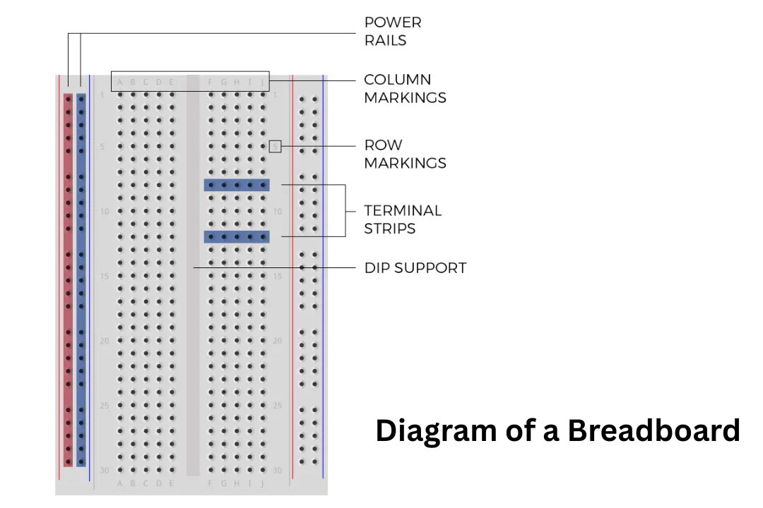
Figure 1: Typical solderless breadboard showing power rails, terminal strips, and central IC channel.
To illustrate the practical usage of a breadboard with a concrete physical example, consider the construction and analysis of a simple RC low-pass filter, which is commonly built on a breadboard in experimental physics and electronics laboratories.