Capacitors
A capacitor is a fundamental passive electronic component used to store electrical energy in the form of an electric field. It consists essentially of two conducting surfaces (plates) separated by an insulating medium known as a dielectric. When a potential difference is applied across the plates, equal and opposite charges accumulate on them, giving rise to an electric field within the dielectric. The ability of a capacitor to store charge per unit potential difference is quantified by its capacitance, measured in farads (F). Capacitors are indispensable in both DC and AC circuits and play a crucial role in signal processing, power conditioning, filtering, timing, coupling, decoupling, and energy storage.
In practical electronic systems, capacitors are used to block direct current while allowing alternating current to pass, smooth out voltage fluctuations in power supplies, tune resonant circuits in radios and communication devices, and provide temporary energy storage in pulsed systems. The behavior of a capacitor depends not only on its capacitance value but also on its dielectric material, construction, voltage rating, frequency response, and temperature stability. These factors give rise to a wide variety of capacitor types, each optimized for specific applications.
Capacitors can broadly be classified based on their dielectric material and construction. Common types include ceramic capacitors, electrolytic capacitors, tantalum capacitors, mica capacitors, paper capacitors, and film capacitors. Each type exhibits distinct electrical characteristics such as dielectric constant, loss tangent, leakage current, equivalent series resistance (ESR), and tolerance. For example, ceramic capacitors are widely used for high-frequency applications due to their low inductance and small size, while electrolytic capacitors are preferred in power supply circuits for their large capacitance values.
An important practical aspect of capacitors is their identification and rating, particularly for small capacitors where printed numerical values may not be feasible. Colour coding provides a standardized method of indicating capacitance value, tolerance, and sometimes voltage rating using colored bands or dots, similar in concept to resistor colour coding. Understanding capacitor colour codes is essential for circuit assembly, maintenance, and troubleshooting, especially in laboratory and educational settings.
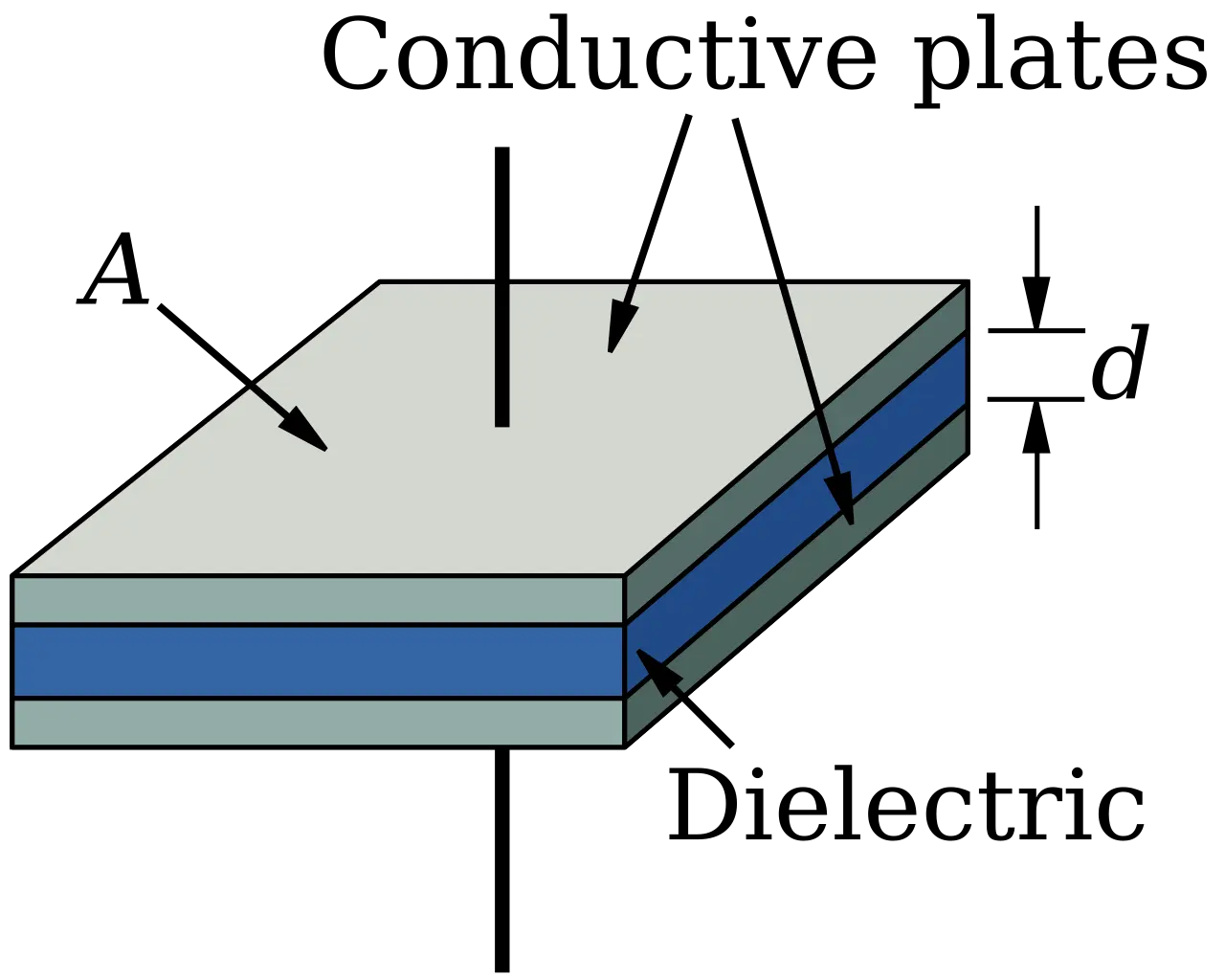
Figure 1: Schematic of a parallel-plate capacitor showing plates and dielectric.
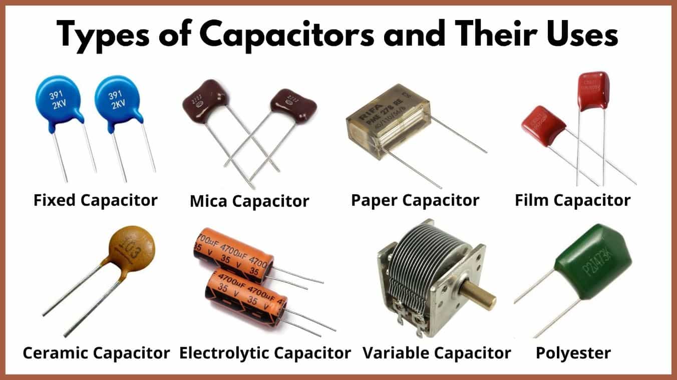
Figure 2: Different capacitor types: ceramic disc, electrolytic capacitor, mica capacitor, and variable capacitor.
Capacitor Colour Coding
Small-value capacitors, particularly older ceramic and mica types, often use a colour-coding scheme to indicate their capacitance value and tolerance when direct numerical marking is impractical. The coding generally consists of coloured dots or bands, each colour corresponding to a numerical digit according to an internationally accepted code. The first two colours represent the significant figures of the capacitance value, the third colour denotes the multiplier (power of ten), and an additional colour may indicate tolerance. The capacitance obtained from colour coding is usually expressed in picofarads (pF).
The standard colour–number correspondence is: black (0), brown (1), red (2), orange (3), yellow (4), green (5), blue (6), violet (7), grey (8), and white (9). For example, a capacitor marked with red–violet–orange corresponds to $ 27 \times 10^{3} \,\text{pF} $, or $ 27 \,\text{nF} $. Tolerance is indicated by an extra colour, such as gold (±5%), silver (±10%), or no colour (±20%). This colour coding system enables quick identification of capacitor values in circuit assembly and maintenance, especially in laboratory and educational environments.
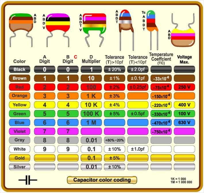
Figure 3: Colour coding scheme for capacitors indicating capacitance value and tolerance.
Full Mathematical Derivation
Consider a parallel-plate capacitor consisting of two conducting plates of area $ A $, separated by a distance $ d $, with a dielectric of permittivity $ \varepsilon = \varepsilon_0 \varepsilon_r $ filling the space between the plates.
Let a charge $ +Q $ be placed on one plate and $ -Q $ on the other. The surface charge density $ \sigma $ on each plate is given by
\[\sigma = \frac{Q}{A}.\]From Gauss’s law in electrostatics,
\[\oint \mathbf{E} \cdot d\mathbf{A} = \frac{Q_{\text{enc}}}{\varepsilon},\]the magnitude of the electric field $ E $ between the plates is
\[E = \frac{\sigma}{\varepsilon} = \frac{Q}{\varepsilon A}.\]The potential difference $ V $ between the plates is related to the electric field by
\[V = \int_0^d E \, dl = Ed = \frac{Qd}{\varepsilon A}.\]By definition, the capacitance $ C $ is the ratio of charge to potential difference:
\[C = \frac{Q}{V}.\]Substituting for $ V $,
\[C = \frac{Q}{\frac{Qd}{\varepsilon A}} = \frac{\varepsilon A}{d}.\]Thus, the capacitance of a parallel-plate capacitor is
\[\boxed{C = \frac{\varepsilon_0 \varepsilon_r A}{d}}.\]This expression shows that capacitance increases with plate area and dielectric constant, and decreases with plate separation.
The energy stored in the capacitor can be derived as follows. The work done $ dW $ in charging the capacitor by an incremental charge $ dq $ when the potential difference is $ v = q/C $ is
\[dW = v \, dq = \frac{q}{C} dq.\]Integrating from $ q = 0 $ to $ q = Q $,
\[W = \int_0^Q \frac{q}{C} dq = \frac{1}{2C} Q^2.\]Using $ Q = CV $, this can also be written as
\[W = \frac{1}{2} CV^2.\]The energy density $ u $ (energy per unit volume) in the electric field is
\[u = \frac{W}{Ad} = \frac{1}{2} \varepsilon E^2,\]demonstrating that the energy is stored in the electric field within the dielectric.
For AC applications, the impedance of an ideal capacitor is
\[Z_C = \frac{1}{j\omega C},\]where $ \omega = 2\pi f $ is the angular frequency. This frequency-dependent behavior explains why capacitors block DC ($ \omega = 0 $) and allow AC to pass.
Real capacitors deviate from ideal behavior due to parasitic resistance (ESR) and inductance (ESL), which become significant at high frequencies and are strongly dependent on capacitor type and construction.