Chokes and Transformers
Chokes and transformers are fundamental electromagnetic components widely used in electrical and electronic systems, particularly in power supplies, communication circuits, and signal-conditioning networks. Both devices operate on the principles of electromagnetic induction and magnetic flux linkage, yet they serve distinct functional roles within circuits. A choke is essentially an inductor designed primarily to impede alternating current (AC) while allowing direct current (DC) to pass with minimal resistance. In contrast, a transformer is a static electrical device that transfers electrical energy between two or more circuits through mutual induction, usually with the purpose of changing voltage or current levels, or providing electrical isolation.
The operation of a choke relies on its inductance, which produces a self-induced electromotive force (emf) opposing changes in current according to Lenz’s law. Because of this property, chokes are especially effective in filtering circuits, where they suppress high-frequency AC components or ripple currents while permitting steady DC components. They are extensively used in power supply filters, radio-frequency (RF) circuits, audio-frequency (AF) circuits, and electromagnetic interference (EMI) suppression. Depending on the frequency range and application, chokes may be classified as AF chokes, RF chokes, or power chokes. The magnetic core material—air, iron, ferrite, or laminated steel—plays a crucial role in determining the inductive behavior and losses of the choke.
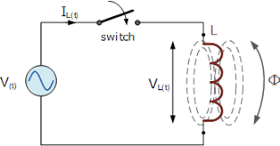
Figure 1: Schematic representation of an inductive choke connected in an AC circuit.
Transformers, on the other hand, consist of two or more windings—typically referred to as the primary and secondary—wound on a common magnetic core. When an alternating voltage is applied to the primary winding, it produces a time-varying magnetic flux in the core, which links the secondary winding and induces an emf in it. The ratio of voltages across the windings depends on the turns ratio, making transformers indispensable for voltage step-up, step-down, impedance matching, and isolation purposes. They are the backbone of electrical power transmission and distribution systems, enabling efficient long-distance power transfer by reducing current and hence minimizing resistive losses.
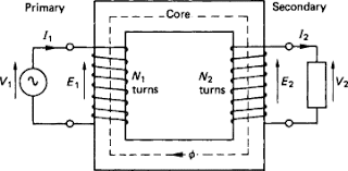
Figure 2: Schematic representation of a transformer showing primary and secondary windings on a common magnetic core.
Full Mathematical Derivation
Consider first a choke, modeled as an ideal inductor of inductance $ L $. According to Faraday’s law of electromagnetic induction, the induced emf $ e $ in a coil is given by
\[e = - \frac{d\Phi}{dt},\]where $ \Phi $ is the magnetic flux linked with the coil. For a coil of $ N $ turns carrying current $ i $, the flux linkage is
\[\lambda = N\Phi = Li.\]Differentiating with respect to time,
\[e = -\frac{d\lambda}{dt} = -L \frac{di}{dt}.\]In an AC circuit with applied voltage $ v(t) = V_0 \sin \omega t $, the governing equation becomes
\[V_0 \sin \omega t = L \frac{di}{dt}.\]Integrating,
\[i(t) = -\frac{V_0}{\omega L} \cos \omega t.\]Thus, the current lags the voltage by $ \pi/2 $, and the magnitude of the inductive reactance is
\[X_L = \omega L.\]This shows mathematically how a choke opposes AC more strongly at higher frequencies, justifying its use in filtering and noise suppression.
Now consider a transformer with a primary winding of $ N_1 $ turns and a secondary winding of $ N_2 $ turns wound on a common magnetic core. Let an alternating voltage $ V_1 $ be applied to the primary. The magnetic flux in the core is assumed to be sinusoidal:
\[\Phi = \Phi_0 \sin \omega t.\]The induced emf in the primary winding is
\[E_1 = -N_1 \frac{d\Phi}{dt} = -N_1 \omega \Phi_0 \cos \omega t.\]For a sinusoidally varying magnetic flux
\[\Phi(t)=\Phi_{\max}\sin\omega t,\]Faraday’s law gives the peak induced emf
\[e_{\max}=N\omega\Phi_{\max}=2\pi f N\Phi_{\max}.\]Since the rms value of a sinusoidal emf is (e_{\max}/\sqrt{2}), we obtain
\[E_{\mathrm{rms}}=\frac{2\pi}{\sqrt{2}}\,fN\Phi_{\max}\approx 4.44\,fN\Phi_{\max}.\]Hence, for the primary and secondary windings respectively,
\[E_1 = 4.44\, f\, N_1\, \Phi_{\max}, \qquad E_2 = 4.44\, f\, N_2\, \Phi_{\max}.\]Taking the ratio,
\[\frac{E_2}{E_1} = \frac{N_2}{N_1}.\]For an ideal transformer, the applied voltage equals the induced emf, so
\[\frac{V_2}{V_1} = \frac{N_2}{N_1}.\]Assuming no losses, power conservation gives
\[V_1 I_1 = V_2 I_2,\]leading to the current ratio
\[\frac{I_2}{I_1} = \frac{N_1}{N_2}.\]This complete derivation establishes the fundamental operating equations of transformers and highlights the dependence of voltage and current transformation on the turns ratio.
Deductions
- A choke offers frequency-dependent opposition to current, making it highly effective for filtering AC ripple while allowing DC to pass.
- The inductive reactance of a choke increases linearly with frequency, which explains its widespread use in RF and noise-suppression circuits.
- A transformer operates solely on alternating or time-varying currents; it cannot function with pure DC due to the absence of changing magnetic flux.
- The voltage transformation ratio of a transformer depends only on the ratio of turns in the secondary and primary windings.
- Ideal transformers conserve power, implying that an increase in voltage is accompanied by a proportional decrease in current.
- Core material and construction significantly affect losses, efficiency, and frequency response in both chokes and transformers.