RF and AF Oscillators
Oscillators are fundamental electronic circuits capable of generating periodic waveforms without the need for an external input signal. They operate by converting direct current (DC) power into alternating current (AC) signals through the use of active devices such as transistors, operational amplifiers, or vacuum tubes, in conjunction with passive components like resistors, capacitors, and inductors. Depending on the frequency range of the generated signal, oscillators are broadly classified into Audio Frequency (AF) oscillators and Radio Frequency (RF) oscillators. AF oscillators typically generate signals in the range of approximately 20 Hz to 20 kHz, which corresponds to the human audible spectrum. These oscillators are widely used in audio signal generators, public address systems, audio testing equipment, and musical instruments. RF oscillators, on the other hand, operate at much higher frequencies, typically from hundreds of kilohertz to several gigahertz, and form the backbone of radio communication systems, including transmitters, receivers, radar, television broadcasting, and wireless communication technologies.
The essential physical principle underlying all oscillators is positive feedback combined with frequency-selective networks. For sustained oscillations to occur, the feedback signal must reinforce the original signal in both magnitude and phase. This requirement is quantitatively described by the Barkhausen criterion, which states that the magnitude of the loop gain must be unity and the net phase shift around the loop must be an integral multiple of $2\pi$.
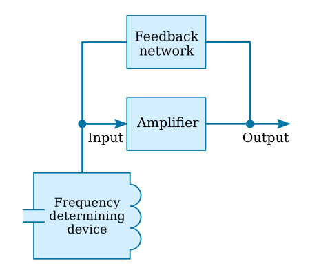
Figure 1: Block diagram of a feedback oscillator
AF oscillators generally employ RC (resistor-capacitor) networks for frequency selection because inductors are bulky and inefficient at low frequencies. Typical AF oscillators include the RC phase-shift oscillator, Wien bridge oscillator, and Twin-T oscillator. RF oscillators, by contrast, rely primarily on LC (inductor-capacitor) resonant circuits or distributed circuit elements, as these are well-suited for high-frequency operation. Common RF oscillators include the Hartley oscillator, Colpitts oscillator, Clapp oscillator, and crystal-controlled oscillators.
The mathematical foundation of both AF and RF oscillators is based on feedback theory. Consider a linear amplifier with open-loop gain $A(\omega)$ and a feedback network with transfer function $\beta(\omega)$. The total loop gain is given by
\[L(\omega) = A(\omega)\beta(\omega).\]For sustained oscillations, the Barkhausen criterion requires
\[|L(\omega_0)| = 1 \quad \text{and} \quad \arg[L(\omega_0)] = 2\pi n,\]where $\omega_0$ is the angular frequency of oscillation and $n$ is an integer.
RC Phase-Shift Oscillator (AF Oscillator)
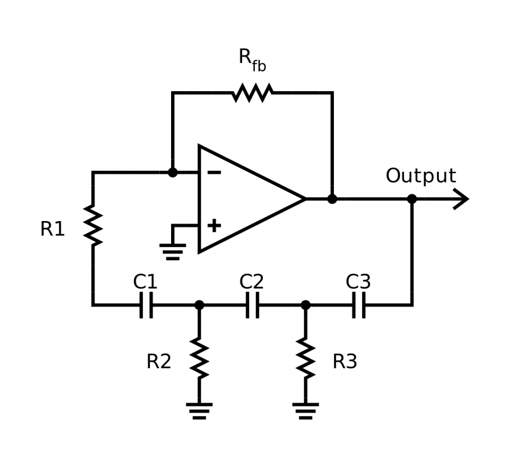
Figure 2: RC phase-shift network used in AF oscillators.
An RC phase-shift oscillator typically consists of an inverting amplifier (providing a phase shift of $\pi$) and a feedback network composed of three identical RC sections, each contributing a phase shift. The total phase shift from the RC network must be $\pi$, so that the overall phase shift around the loop is $2\pi$.
For a single RC section, the phase shift is
\[\phi = \tan^{-1}(\omega RC).\]For three identical sections,
\[3\phi = \pi \quad \Rightarrow \quad \phi = \frac{\pi}{3}.\]Thus,
\[\tan\left(\frac{\pi}{3}\right) = \omega RC \quad \Rightarrow \quad \omega = \frac{1}{\sqrt{3}RC}.\]Hence, the frequency of oscillation is
\[f = \frac{1}{2\pi\sqrt{3}RC}.\]The magnitude condition yields the required gain of the amplifier. For three RC sections, the attenuation of the feedback network is $1/29$, so the amplifier gain must satisfy
\[A \geq 29.\]LC Oscillator (RF Oscillator)

Figure 3: LC tank circuit used in RF oscillators.
Consider an LC tank circuit consisting of an inductor $L$ and a capacitor $C$. The impedance of the inductor is $j\omega L$, and that of the capacitor is $-j/(\omega C)$. At resonance, the net reactance is zero:
\[\omega L = \frac{1}{\omega C}.\]Solving for $\omega$,
\[\omega_0 = \frac{1}{\sqrt{LC}}.\]Therefore, the frequency of oscillation is
\[f_0 = \frac{1}{2\pi\sqrt{LC}}.\]In practical RF oscillators such as the Colpitts oscillator, the feedback network is realized using a capacitive voltage divider. Let the capacitors be $C_1$ and $C_2$. The effective capacitance of the tank circuit is
\[C_{\text{eq}} = \frac{C_1 C_2}{C_1 + C_2}.\]Thus, the oscillation frequency becomes
\[f_0 = \frac{1}{2\pi\sqrt{L C_{\text{eq}}}}.\]The gain condition is satisfied by ensuring that the amplifier compensates for losses in the LC circuit. Any deviation from resonance results in a phase mismatch, suppressing oscillations at unwanted frequencies. This frequency-selective behavior is central to RF oscillator stability.
Deductions
- AF oscillators primarily use RC networks, while RF oscillators rely on LC or crystal-based resonant circuits due to frequency-dependent component behavior.
- The Barkhausen criterion provides a universal condition for oscillation, independent of the specific circuit topology.
- Frequency stability in RF oscillators is more critical than in AF oscillators, leading to the widespread use of crystal oscillators.