Resistors
Resistors: Types, Characteristics, and Colour Coding
A resistor is one of the most fundamental passive components used in electrical and electronic circuits. Its primary function is to oppose or limit the flow of electric current, thereby controlling voltage levels, dividing currents, reducing power, and protecting sensitive components. Resistors operate based on the principle that certain materials inherently resist the motion of electrons. This resistance is quantified in ohms (Ω), named after Georg Simon Ohm, who formulated the foundational relationship among voltage (V), current (I), and resistance (R).
In practical electronics, resistors are indispensable because they help manage power distribution, set biasing conditions for transistors, determine time constants in RC circuits, and stabilize amplifier gains. They appear in diverse forms depending on their intended application, construction, and required precision. Modern resistors are manufactured using materials such as carbon composition, carbon film, metal film, metal oxide, and wire wound alloys. Each of these types exhibits different characteristics related to stability, tolerance, temperature coefficient, noise performance, and power handling capability.
Resistor characteristics define their suitability in specific circuits. The main characteristics include resistance value, tolerance, power rating, temperature coefficient of resistance (TCR), noise behavior, and frequency response. Power rating indicates how much heat a resistor can dissipate without damage. Tolerance specifies the permissible deviation from the labeled resistance value, while temperature coefficient quantifies how resistance changes with temperature. For high-frequency or precision circuits, these characteristics become especially critical.
A widely used system for marking resistor values is the colour coding scheme, particularly for through-hole cylindrical resistors. This system uses bands of different colours to encode numerical resistance values and tolerance. Each colour represents a specific digit or multiplier, and by reading the bands in sequence, the value can be decoded quickly. For modern SMD resistors, numerical codes replace colour coding, but the principle remains the same.
To understand resistor behaviour mathematically, we begin with Ohm’s Law, which forms the basis of linear resistor operation.
1. Ohm’s Law
The fundamental relationship is:
\[V = IR\]where
$ V $ = voltage across resistor (volts),
$ I $ = current flowing through resistor (amperes),
$ R $ = resistance (ohms).
2. Power Dissipation Derivation
Power dissipated by a resistor due to current flow is given by:
\[P = IV\]Substituting Ohm’s law $ V = IR $:
\[P = I(IR) = I^{2}R\]Alternatively, using $ I = \frac{V}{R} $:
\[P = V \left( \frac{V}{R} \right) = \frac{V^{2}}{R}\]Thus, power dissipation has three equivalent forms:
\[P = VI,\quad P = I^{2}R,\quad P = \frac{V^{2}}{R}\]3. Temperature Dependence of Resistance
Many resistors exhibit a linear temperature dependence:
\[R_T = R_0 (1 + \alpha \Delta T)\]where
$ R_T $ = resistance at temperature $ T $,
$ R_0 $ = resistance at reference temperature,
$ \alpha $ = temperature coefficient of resistance (TCR),
$ \Delta T = T - T_0 $.
This expression demonstrates that resistance increases or decreases depending on whether the resistor material exhibits positive or negative TCR.
4. Series and Parallel Combinations
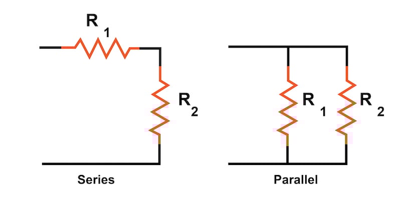
Series:
\[R_{\text{eq}} = R_1 + R_2 + R_3 + \cdots\]Parallel:
\[\frac{1}{R_{\text{eq}}} = \frac{1}{R_1} + \frac{1}{R_2} + \frac{1}{R_3} + \cdots\]or for two resistors:
\[R_{\text{eq}} = \frac{R_1 R_2}{R_1 + R_2}\]5. Colour Code Interpretation (Mathematical)
A resistor with colour bands $ B_1, B_2, B_3, B_4 $ is interpreted as:
\[R = (10 \times D_1 + D_2) \times 10^{M} \ \Omega\]where
$ D_1 $ = digit from first band,
$ D_2 $ = digit from second band,
$ M $ = multiplier from third band,
fourth band gives tolerance.
Diagram of a typical resistor showing colour bands and orientation.

Example:
Red (2), Violet (7), Yellow ($10^4$), Gold (±5%)