Star & Delta Connection
Star (also called Wye or Y) and Delta (Δ) connections are fundamental network configurations used extensively in electrical engineering, circuit design, and power system analysis. These connections help simplify complex three-phase networks, making them easier to analyze for voltage, current, impedance, and power calculations. The star connection consists of three circuit elements whose one end is connected to a common junction known as the star point or neutral point, while the other ends form the three independent phase terminals. This configuration resembles the shape of the letter ‘Y’. It is widely used in power transmission systems, distribution networks, and balanced load connections due to its ability to provide two voltage levels—phase and line voltages.
In contrast, the delta connection forms a closed loop that resembles a triangle. Here, each of the three elements connects end-to-end such that the junction of any two elements forms a phase terminal. Delta connections do not have a neutral point, and all three wires carry the phase currents. This setup is commonly found in motor windings, transformers for high-power applications, and circuits requiring higher starting torque or robustness under unbalanced loads. One of the main advantages of delta configuration is that the line voltage and phase voltage remain equal, simplifying certain types of power analysis.
The importance of star and delta connections extends beyond resistive networks; they are equally applicable to capacitors and inductors. The transformation between star and delta (and vice versa) helps reduce complex circuit networks into simpler equivalent circuits. For resistors, the star-to-delta (Y–Δ) and delta-to-star (Δ–Y) transformations allow conversion of networks that cannot be simplified using series or parallel rules alone. These transformations are vital tools in network analysis, especially when dealing with bridge circuits or irregular mesh topologies.

Similarly, capacitors and inductors also follow analogous transformation rules, although the formulas differ due to the impedance behavior of reactive components. In a star-connected capacitor network, equivalent capacitance behaves differently compared to a delta-connected network—mainly reversing the mathematical pattern seen in resistors. For inductors, since the inductive reactance is proportional to frequency, star–delta transformations are especially useful in AC circuit analysis, resonant circuits, impedance matching, and filter design.
In three-phase systems, star and delta connections significantly influence the resulting voltages, currents, and power distribution. For example, in star connections, the line voltage is √3 times the phase voltage, allowing systems to operate at lower insulation requirements since individual elements experience lower voltage. Meanwhile, delta connections provide higher line currents for the same element rating due to the √3 factor difference between line and phase currents. These relationships influence the design of power transmission systems, motor starting methods, and transformer windings. Star connections are generally preferred for long-distance transmission due to lower power loss, while delta connections are more suitable for short-distance, high-power applications.
Three-Phase Electrical Terms
In three-phase electrical engineering, several key terms describe how voltages and currents behave depending on whether the system is connected in a Star (Y) or Delta (Δ) configuration. The proper understanding of line voltage, phase voltage, line current, phase current, neutral point, and phase sequence is essential for analyzing power systems, transformers, motors, and three-phase loads. These terms determine the magnitude of electrical quantities delivered to devices, the insulation required, the current distribution, and the total power transfer capability of the system. Because three-phase systems consist of three sinusoidal voltages displaced by 120° from one another, the way these voltages are connected affects the resulting relationship between line and phase quantities.
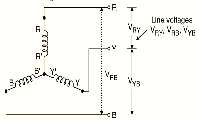
Line Voltage ( $ V_L $ ) refers to the voltage measured between any two of the three line conductors in a three-phase system (e.g., between R–Y, Y–B, or B–R). This is the voltage typically available for industrial loads or for interconnection between electrical equipment.
Phase Voltage ( $ V_P $ ), however, is the voltage appearing across a single phase element of the load or transformer winding. In a star-connected system, the phase voltage is lower because each phase is connected from the line to the neutral point. This relationship creates the well-known equation $ V_L = \sqrt{3}\, V_P $ as shown in figure below.
In delta systems, the phase voltage is directly across each closed-loop branch, which also happens to be the voltage between any two lines, making $ V_L = V_P $.
Line Current ( $ I_L $ ) is the current flowing through each of the line conductors.
Phase Current ( $ I_P $ ) is the current flowing through each individual load element (resistor, inductor, capacitor, or transformer winding). In star connections, since each line conductor is directly connected to one of the phase windings, line and phase currents are identical: $ I_L = I_P $. In a delta connection, each line conductor supplies the current for two branches of the delta loop, resulting in the relationship $ I_L = \sqrt{3}\, I_P $. Thus, delta systems carry higher line currents but operate at the same voltage in each branch.
The neutral point exists only in star connections, where the three phase ends meet. It provides a return path for unbalanced loads and allows both single-phase and three-phase voltages to be supplied simultaneously. Delta connections lack a neutral, meaning loads must be balanced to avoid circulating currents. Another important term is the phase sequence, which refers to the order in which voltages reach their maximum value (e.g., R-Y-B or R-B-Y). Phase sequence determines the direction of rotation of three-phase motors and ensures proper synchronisation between generators and power grids.
Three-phase power also depends on these quantities. The total power delivered is given by:
\[P = \sqrt{3}\, V_L I_L \cos\phi = 3 V_P I_P \cos\phi,\]showing the equivalence of star and delta formulas when correct relations are applied. These relationships form the foundation of power system engineering and allow safe, reliable, and predictable operation of three-phase equipment.
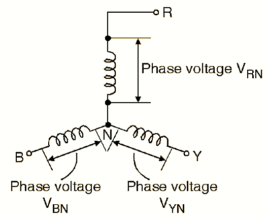
Derivation of Line and Phase Voltage Relation in Star (Y) Connection
In a star system, phase voltage is between a line conductor and neutral:
\[V_{RN} = V_P,\quad V_{YN} = V_P,\quad V_{BN} = V_P.\]Line voltage is measured between two lines, e.g., between R and Y:
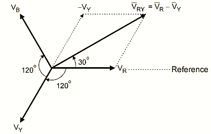
\[V_{RY} = V_{RN} - V_{YN}.\]Represent phase voltages as 120°-displaced phasors:
\[V_{RN} = V_P \angle 0^\circ,\quad V_{YN} = V_P \angle -120^\circ.\]Thus,
\[V_{RY} = V_P\angle 0^\circ - V_P\angle -120^\circ.\]Compute magnitude:
\[|V_{RY}| = \sqrt{V_P^2 + V_P^2 - 2V_P^2\cos(120^\circ)} = \sqrt{3V_P^2} = \sqrt{3}V_P.\]Hence,
\[V_L = \sqrt{3}\, V_P.\]Derivation of Line and Phase Current Relation in Delta (Δ) Connection
In delta, phase voltage = line voltage:
\[V_{P} = V_L.\]But each line current is the vector sum of currents of two delta branches:
\[I_L = |I_{12} - I_{31}|.\]Using phasor separation of 120°:
\[I_L = \sqrt{3} I_P.\]Thus delta carries larger line current.
Star–Delta (Y–Δ) Transformation for Resistors
Consider a star network with resistances $ R_1, R_2, R_3 $ connected to a central neutral point. The equivalent delta network contains resistances $ R_{12}, R_{23}, R_{31} $.
The Δ resistances are given by:
Conversely, the Y resistances from Δ network:
\[R_1 = \frac{R_{12} R_{31}}{R_{12} + R_{23} + R_{31}},\] \[R_2 = \frac{R_{12} R_{23}}{R_{12} + R_{23} + R_{31}},\] \[R_3 = \frac{R_{23} R_{31}}{R_{12} + R_{23} + R_{31}}.\]Star–Delta Transformation for Capacitors
For capacitors, since their equivalent impedance behaves inversely to capacitance:
\[C_{12} = \frac{C_1 C_2}{C_1 + C_2 + C_3},\] \[C_{23} = \frac{C_2 C_3}{C_1 + C_2 + C_3},\] \[C_{31} = \frac{C_3 C_1}{C_1 + C_2 + C_3}.\]The reverse Δ–Y transformation:
\[C_1 = \frac{C_{12} + C_{31} - C_{23}}{2},\] \[C_2 = \frac{C_{12} + C_{23} - C_{31}}{2},\] \[C_3 = \frac{C_{23} + C_{31} - C_{12}}{2}.\]Star–Delta Transformation for Inductors
Inductors follow the same pattern as resistors because inductive reactance $ X_L = \omega L $ is proportional to $ L $:
\[L_{12} = \frac{L_1 L_2 + L_2 L_3 + L_3 L_1}{L_3},\] \[L_{23} = \frac{L_1 L_2 + L_2 L_3 + L_3 L_1}{L_1},\] \[L_{31} = \frac{L_1 L_2 + L_2 L_3 + L_3 L_1}{L_2}.\]Reverse transformation:
\[L_1 = \frac{L_{12} L_{31}}{L_{12} + L_{23} + L_{31}}, \quad \text{etc.}\]Transformer Star and Delta Relationships
For three-phase transformers:
-
Star (Y): \(V_L = \sqrt{3} V_P, \quad I_L = I_P\)
-
Delta (Δ): \(V_L = V_P, \quad I_L = \sqrt{3} I_P\)
Three-phase power:
\[P = \sqrt{3} V_L I_L\cos\phi = 3 V_P I_P \cos\phi.\]These transformations allow equivalent modeling of transformer windings and other AC systems.