

28 Jun 2025
Michelson and Fabry-Perot Interferometers
Interferometer geometry, Michelson fringes and measurements, the Michelson-Morley null result, and Fabry-Perot multiple-beam interference.
Michelson interferometer
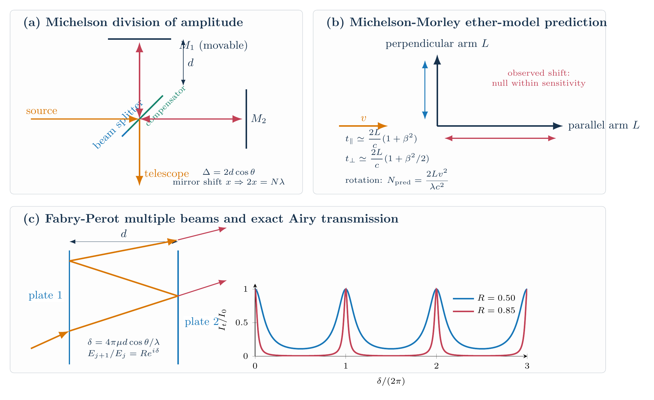
A half-silvered plate divides the incident amplitude into two perpendicular arms. After reflection at mirrors $M_1$ and $M_2$, the beams return and recombine. A compensating plate of the same glass and thickness makes both beams traverse equal glass paths, preventing an unwanted wavelength-dependent phase difference.
The two returning waves behave as if they came from $M_1$ and the virtual image $M_2^{\prime}$ of the other mirror. If the effective separation of these parallel surfaces is $d$, a ray observed at angle $\theta$ has the round-trip optical-path difference
\[\boxed{\Delta=2d\cos\theta}.\]A fixed phase added by the beam splitter may exchange bright and dark labels, but it does not change fringe spacing or any measurement below. Equal-inclination fringes satisfy
\[\boxed{2d\cos\theta_m=m\lambda}.\]For parallel effective mirrors, the fringes are circular. If the mirrors are slightly inclined, localized nearly straight fringes of equal thickness are obtained.
Wavelength
Moving one physical mirror by $x$ changes its round-trip path by $2x$. If $N$ fringes cross a reference point,
\[2x=N\lambda,\]so
\[\boxed{\lambda=\frac{2x}{N}}.\]The distance $x$ and wavelength $\lambda$ must be expressed in the same length unit.
Difference of two nearby wavelengths
At normal observation, the phase for wavelength $\lambda_i$ is $\phi_i=4\pi d/\lambda_i$. Let $\Delta x$ be the mirror displacement between successive revivals of maximum visibility. The relative phase must change by $2\pi$:
\[4\pi\Delta x\left\lvert\frac1{\lambda_1}-\frac1{\lambda_2}\right\rvert=2\pi.\]Therefore
\[2\Delta x\left\lvert\frac1{\lambda_1}-\frac1{\lambda_2}\right\rvert=1.\]For $\lambda_1\simeq\lambda_2\simeq\bar\lambda$,
\[\left\lvert\frac1{\lambda_1}-\frac1{\lambda_2}\right\rvert =\frac{\lvert\lambda_1-\lambda_2\rvert}{\lambda_1\lambda_2} \simeq\frac{\lvert\lambda_1-\lambda_2\rvert}{\bar\lambda^2},\]hence
\[\boxed{\lvert\lambda_1-\lambda_2\rvert \simeq\frac{\bar\lambda^2}{2\Delta x}}.\]Refractive index
Insert a cell of internal length $t$ into one arm. Replacing air by a medium of index $\mu$ changes the one-way optical path by $(\mu-1)t$, and the beam passes through the cell twice. If $N$ fringes shift,
\[N\lambda=2t(\mu-1),\]so
\[\boxed{\mu=1+\frac{N\lambda}{2t}}.\]The visibility is
\[\mathcal V=\frac{I_{\max}-I_{\min}}{I_{\max}+I_{\min}},\]and is greatest when the returning intensities are equal and their optical-path difference lies within the source’s coherence length.
Michelson-Morley experiment and its null result
The historical stationary-ether model assigned the apparatus speed $v$ through the ether. For an arm of length $L$ parallel to $v$, the predicted round-trip time was
\[t_\parallel=\frac{L}{c-v}+\frac{L}{c+v} =\frac{2Lc}{c^2-v^2}.\]With $\beta=v/c\ll1$ and $(1-\beta^2)^{-1}\simeq1+\beta^2$,
\[t_\parallel\simeq\frac{2L}{c}(1+\beta^2).\]For the perpendicular arm, the ether-model transverse construction gave an effective transverse speed $\sqrt{c^2-v^2}$, so
\[t_\perp=\frac{2L}{\sqrt{c^2-v^2}} =\frac{2L}{c}(1-\beta^2)^{-1/2} \simeq\frac{2L}{c}\left(1+\frac{\beta^2}{2}\right).\]Thus
\[\Delta t=t_\parallel-t_\perp \simeq\frac{Lv^2}{c^3}.\]Rotating the apparatus through $90^\circ$ interchanges the arms and reverses this difference. The predicted optical-path change and fringe shift were therefore
\[\Delta_{\rm rot}=2c\Delta t=\frac{2Lv^2}{c^2}, \qquad \boxed{N_{\rm predicted}=\frac{2Lv^2}{\lambda c^2}}.\]The predicted ether-wind shift was not observed. This was a failure of the stationary-ether prediction, not a failure of the interferometer.
Fabry-Perot interferometer
Two parallel, partially reflecting plates enclose a medium of index $\mu$ and separation $d$. Successive transmitted beams differ by one round trip, so their phase difference is
\[\boxed{\delta=\frac{4\pi\mu d\cos\theta}{\lambda}}.\]For identical lossless plates of intensity reflectance $R$, each additional transmitted field is multiplied in magnitude by $R$ and in phase by $e^{i\delta}$. Thus
\[E_t=E_a\left(1+Re^{i\delta}+R^2e^{2i\delta}+\cdots\right) =\frac{E_a}{1-Re^{i\delta}}.\]The first transmitted intensity contributes the factor $(1-R)^2$. Therefore
\[\frac{I_t}{I_0} =\frac{(1-R)^2}{\lvert1-Re^{i\delta}\rvert^2} =\frac{(1-R)^2}{1+R^2-2R\cos\delta}.\]Using $1-\cos\delta=2\sin^2(\delta/2)$ gives the Airy formula
\[\boxed{\frac{I_t}{I_0} =\frac{1}{1+F\sin^2(\delta/2)}}, \qquad \boxed{F=\frac{4R}{(1-R)^2}}.\]Transmission maxima occur when
\[\boxed{2\mu d\cos\theta=m\lambda}.\]As $R$ increases, the Airy maxima become narrower while their normalized peak value remains one, allowing closer spectral features to be distinguished.
Solved Problems
Problem 1: Separation of a close spectral doublet
Successive visibility maxima occur after a Michelson mirror displacement $\Delta x=0.180\,\mathrm{mm}$ for a doublet near $\bar\lambda=600\,\mathrm{nm}$. Find the wavelength separation.
The recurrence condition is
\[2\Delta x\left\lvert \frac1{\lambda_1}-\frac1{\lambda_2} \right\rvert=1.\]For a close doublet,
\[\left\lvert \frac1{\lambda_1}-\frac1{\lambda_2} \right\rvert \simeq\frac{\Delta\lambda}{\bar\lambda^2},\]so
\[\Delta\lambda \simeq\frac{\bar\lambda^2}{2\Delta x} =\frac{(600\times10^{-9})^2} {2(0.180\times10^{-3})} =1.00\times10^{-9}\,\mathrm m.\]Hence $\boxed{\Delta\lambda\simeq1.00\,\mathrm{nm}}$. The ratio $\Delta\lambda/\bar\lambda=1/600\ll1$ validates the close-doublet approximation.
Problem 2: Minimum Fabry-Perot transmission
Show that the normalized transmission minimum of a lossless symmetric Fabry-Perot interferometer is
\[\left(\frac{1-R}{1+R}\right)^2,\]and evaluate it for $R=0.80$.
At an antiresonance, $\delta=(2m+1)\pi$, hence $\sin^2(\delta/2)=1$. The Airy formula gives
\[\frac{I_{\min}}{I_0} =\frac{1}{1+F}, \qquad F=\frac{4R}{(1-R)^2}.\]Therefore
\[\begin{aligned} \frac{I_{\min}}{I_0} &=\frac{1}{1+4R/(1-R)^2}\\ &=\frac{(1-R)^2}{(1-R)^2+4R} =\boxed{\left(\frac{1-R}{1+R}\right)^2}. \end{aligned}\]For $R=0.80=4/5$,
\[\frac{I_{\min}}{I_0} =\left(\frac{1/5}{9/5}\right)^2 =\boxed{\frac1{81}\simeq0.0123}.\]Descriptive Questions
- Why is a compensating plate used in a Michelson interferometer?
- Under what mirror conditions does a Michelson interferometer show circular or nearly straight fringes?
- What stationary-ether prediction failed in the Michelson-Morley experiment, and what did the null result mean?
- Why do Fabry-Perot transmission peaks become sharper as plate reflectance increases?
Numerical Problems
-
In a Michelson interferometer, $400$ fringes cross the field when one mirror is moved. For $\lambda=500\,\mathrm{nm}$, use $2x=N\lambda$.
Answer: $\boldsymbol{x=0.100\,\mathrm{mm}}$.
-
A $5.00\,\mathrm{cm}$ gas cell inserted in one arm produces $120$ fringe shifts at $\lambda=600\,\mathrm{nm}$. Use $\mu=1+N\lambda/(2t)$.
Answer: $\boldsymbol{\mu=1.00072}$.
-
The stationary-ether model uses $L=11.0\,\mathrm m$, $v=30.0\,\mathrm{km\,s^{-1}}$, $\lambda=500\,\mathrm{nm}$, and $c=3.00\times10^8\,\mathrm{m\,s^{-1}}$. Evaluate $N=2Lv^2/(\lambda c^2)$.
Answer: $\boldsymbol{N_{\mathrm{predicted}}=0.440\ \text{fringe}}$.
-
At normal incidence, adjacent Fabry-Perot resonances satisfy $2d\nu_m/c=m$. An air-spaced etalon has plate separation $d=1.50\,\mathrm{cm}$. Find its free spectral range $\Delta\nu=\nu_{m+1}-\nu_m$.
Answer: $\boldsymbol{\Delta\nu=10.0\,\mathrm{GHz}}$.
The measurement formulae, small-$v/c$ expansions, Airy sum, and all worked answers are checked in the Unit II Maxima worksheet.


Discussion