

17 May 2025
8085 Arithmetic and Logical Instructions with Flags
Opcode construction, exact flag semantics, accumulator operations, BCD correction and 8085 cycle timing for arithmetic and logic.
The 8085 arithmetic and logical unit operates principally on the accumulator. Most 8-bit operations replace A by an 8-bit result and encode properties of that result in five condition flags. Those flags connect computation to conditional control flow, so a correct program must track both the value and the flag side effects of every intervening instruction.
In the flag byte, the defined bits are
\[\boxed{D_7=S,\quad D_6=Z,\quad D_4=AC,\quad D_2=P, \quad D_0=CY}.\]The other positions are filler bits when flags are represented as a complete program-status-word byte. Intel leaves $D_5,D_3,D_1$ undefined on the 8085, so software must not test a fixed filler pattern. S copies result bit 7; Z=1 exactly when the 8-bit result is zero; P=1 for an even number of one bits; CY records carry from bit 7 for addition and functions as a borrow indication for subtraction; AC records the processor’s auxiliary carry associated with bit 3 and supports decimal adjustment.
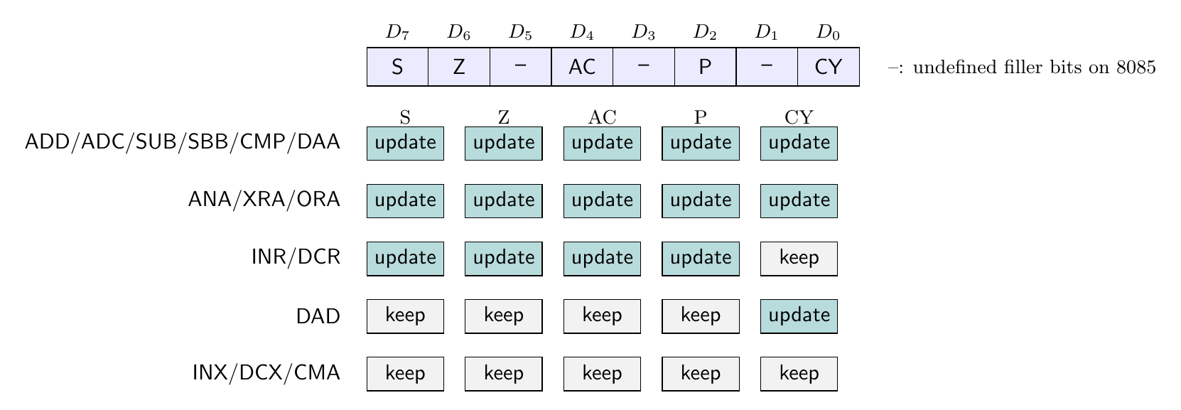
Regular accumulator opcode groups
The register/memory arithmetic and logical families share the form
\[\boxed{10\,OOO\,SSS},\]where SSS is 000,001,010,011,100,101,110,111 for B,C,D,E,H,L,M,A. The operation field is
OOO |
000 | 001 | 010 | 011 | 100 | 101 | 110 | 111 |
|---|---|---|---|---|---|---|---|---|
| Operation | ADD |
ADC |
SUB |
SBB |
ANA |
XRA |
ORA |
CMP |
For example, ADC E is 10 001 011 = 8BH, and CMP M is 10 111 110 = BEH. A register operand gives 1 byte, 1 machine cycle and 4 T-states. M gives 1 byte, 2 cycles and 7 T-states because the memory byte at HL must be read.
The immediate variants have form 11 OOO 110: ADI C6H, ACI CEH, SUI D6H, SBI DEH, ANI E6H, XRI EEH, ORI F6H, and CPI FEH. Each includes one data byte and therefore uses 2 bytes, 2 machine cycles and 7 T-states.
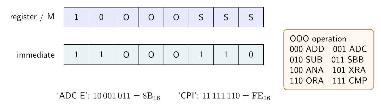
Addition and carry propagation
ADD source performs $A\leftarrow A+\text{source}$; incoming CY is ignored. ADC source performs
so it propagates a carry from a preceding lower-order byte. ADI and ACI use the second instruction byte instead of a register or memory source. All five flags S,Z,AC,P,CY are updated.
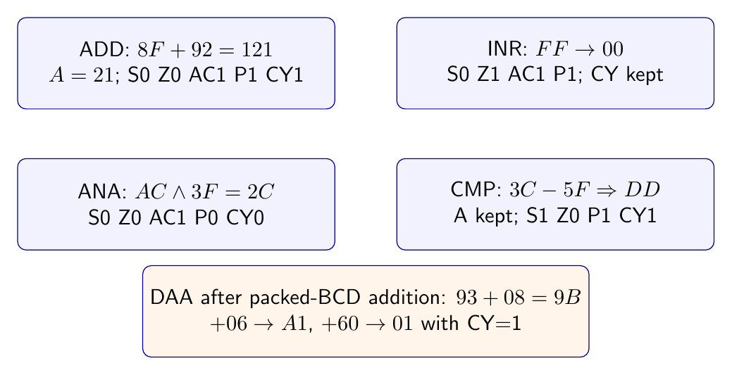
Take A=8FH and B=92H. ADD B forms
The stored result is 21H. There is a carry out of bit 7, so CY=1; FH+2H produces a nibble carry, so AC=1; bit 7 of 21H is zero, hence S=0; the result is nonzero, hence Z=0; and 21H has two one bits, hence P=1.
For multi-byte unsigned addition, add the least-significant bytes with ADD and all higher bytes with ADC. If HL=FFFFH and DE=0001H, one bytewise implementation adds L+E, stores the low result, then adds H+D+CY. The final CY=1 represents overflow beyond sixteen bits. The 8085 has no separate signed-overflow condition flag; CY alone must not be interpreted as signed overflow.
Subtraction, borrow and comparison
SUB source performs $A\leftarrow A-\text{source}$ and ignores the incoming carry. SBB source performs
using CY as the incoming borrow. SUI and SBI are the immediate forms. Intel describes subtraction as two’s-complement addition and complements the final carry to form the borrow flag: CY=1 means that an unsigned borrow was required.
Auxiliary carry during subtraction follows the internal two’s-complement addition; it should not be guessed from the final decimal appearance. For example, Intel’s SUB A example produces zero and CY=0, but AC=1 because the internal addition carries out of bit 3. This distinction matters if DAA or a saved PSW follows.
CMP source and CPI data perform the same flag-producing subtraction as SUB and SUI, but discard the result and leave A unchanged. If A=3CH and E=5FH, CMP E tests the conceptual result DDH: Z=0, S=1, CY=1, and parity is even. Thus unsigned relations can be read as: equality from Z=1, A<operand from CY=1, and A\geq operand from CY=0. CMP r is 1 byte/4 T-states, CMP M is 1 byte/7 T-states, and CPI is 2 bytes/7 T-states.
Increment, decrement and 16-bit arithmetic
INR r and DCR r are one-byte register operations taking 1 cycle and 4 T-states. They affect S,Z,AC,P but preserve CY. INR M and DCR M are read-modify-write instructions: opcode fetch, memory read at HL, and memory write at HL, totaling 3 machine cycles and 10 T-states.
Carry preservation is deliberate. If CY=1 and A=FFH, INR A produces 00H with Z=1, S=0, P=1, AC=1, while CY remains 1. Therefore INR cannot replace ADI 1 in code that expects the carry-out of the increment.
INX rp and DCX rp change a 16-bit register pair or SP without changing any flags. Each is 1 byte, 1 machine cycle and 6 T-states on the 8085. DAD rp adds BC,DE,HL or SP to HL; it is 1 byte, 3 cycles and 10 T-states, and affects only CY. The low byte of the 16-bit result goes to L, the high byte to H.
Boolean operations and masks
ANA/ANI performs bitwise AND, updates S,Z,P, clears CY, and on the 8085 always sets AC. This last rule differs from the 8080 rule and must be treated as an architectural 8085 property. With A=ACH, ANI 3FH gives 2CH; it has odd parity, so P=0, while CY=0 and AC=1.
XRA/XRI performs exclusive OR and resets both CY and AC. XRA A is therefore a one-byte, four-state way to obtain A=00H, with Z=1, P=1, S=0, CY=0, AC=0. ORA/ORI performs inclusive OR and also resets CY and AC. AND clears selected bits with zero mask positions, OR sets selected bits with one mask positions, and XOR toggles selected bits with one mask positions.
Rotate, complement and decimal adjustment
RLC and RRC rotate the accumulator circularly; the bit leaving one end is copied both to CY and the opposite end. RAL and RAR rotate through the carry, treating CY and the accumulator as a nine-bit path. Each is 1 byte, 1 cycle and 4 T-states and affects only CY. CMA complements all accumulator bits in 4 T-states and affects no flag. STC sets CY; CMC complements it; neither alters the other flags.
DAA is a one-byte, four-state instruction used after addition of packed BCD operands. If the low nibble exceeds 9 or AC=1, it adds 06H; if the high nibble exceeds 9 or CY=1, it adds 60H. It affects all five flags. In Intel’s example,
so the decimal result is 101, with the hundreds carry represented by CY.
Timing and flag analysis must follow the actual operand location. For example, ADD M and ADI d8 both require seven T-states, but their second cycles address different sources: ADD M reads the effective address in HL, whereas ADI reads the instruction byte at PC. Both update all five flags. By contrast, DCR M takes ten T-states because it reads and rewrites the addressed byte, yet it deliberately preserves CY. Therefore identical timing does not imply identical bus traffic, and similar arithmetic notation does not imply identical flag effects.
The operation, flag and timing rules above follow Intel’s 8080/8085 Assembly Language Programming Manual (November 1978), including its explicit 8085 rule for auxiliary carry after logical AND.
Preparation questions
- Construct the opcodes and state the timings of
SBB L,SBB MandSBI 20H. - For
A=8FH,B=92H, independently verify all five flags afterADD B. - Explain why
INR Acannot be substituted forADI 01Hwhen carry propagation is required. - Starting with
A=3CH, determine the branch conditions established byCPI 5FHwithout changingA. - Compare the flag effects of
ANA,XRAandORA, paying particular attention toACon the 8085. - Trace
RALforA=85H, first withCY=0and then withCY=1. - Apply Intel’s two-stage
DAArule to packed-BCD addition58+76and identify the final carry.


Discussion