

19 May 2025
8085 Branch, I/O and Machine-Control Instructions
Conditional control flow, calls and returns, restart vectors, isolated I/O, interrupt control and exact path-dependent 8085 timing.
Branch instructions change the program counter, I/O instructions exchange a byte with the isolated port space, and machine-control instructions alter the processor’s operating state. These groups generally do not modify condition flags. Conditional branches instead read flags left by a preceding arithmetic or logical instruction, so a transfer or control instruction may be deliberately placed between the test-producing operation and the branch when its documented flag effect is none.
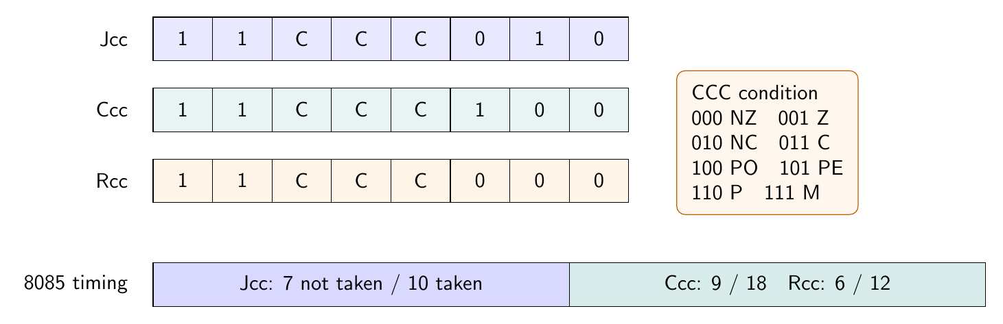
Condition codes and opcode construction
The eight branch conditions use a common three-bit field:
CCC |
000 | 001 | 010 | 011 | 100 | 101 | 110 | 111 |
|---|---|---|---|---|---|---|---|---|
| Condition | NZ | Z | NC | C | PO | PE | P | M |
| Test | $Z=0$ | $Z=1$ | $CY=0$ | $CY=1$ | $P=0$ | $P=1$ | $S=0$ | $S=1$ |
Conditional jump, call and return opcodes are respectively
\[\boxed{11\,CCC\,010},\qquad \boxed{11\,CCC\,100},\qquad \boxed{11\,CCC\,000}.\]For example, JZ uses CCC=001, so its opcode is 11001010B=CAH; CPE is 11101100B=ECH; and RNC is 11010000B=D0H. The instructions only test the selected flag. They do not clear, complement or otherwise consume it.
Jumps and the program counter
JMP address has opcode C3H. It is 3 bytes, 3 machine cycles and 10 T-states. Its address is encoded low byte first: JMP 3456H becomes C3 56 34, and execution continues with the opcode at 3456H.
Every conditional jump also occupies 3 bytes in memory. On the 8085, however, timing depends on the result. A false condition uses 2 machine cycles and 7 T-states; a true condition uses 3 cycles and 10 T-states. Intel specifies that the processor fetches the third instruction byte only when the condition is satisfied. If JNZ 3456H begins at 2000H, the not-taken path still continues at 2003H; the high target byte at 2002H is skipped rather than used as the next opcode. The taken path loads PC=3456H.
PCHL (E9H) is an indirect unconditional branch: it copies HL to PC. It is 1 byte, 1 machine cycle and 6 T-states. Unlike JMP, the destination is not present in the instruction stream. PCHL changes no flags and pushes no return address.
Calls, returns and stack order
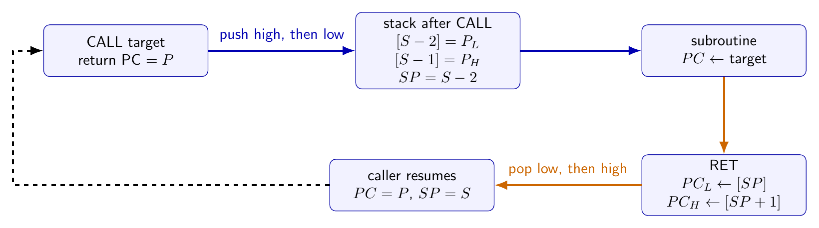
CALL address (CDH) first establishes the address of the next sequential instruction, pushes that 16-bit return address, then loads the target into the PC. It is 3 bytes, 5 machine cycles and 18 T-states on the 8085. If SP=S before the call and the return address is P, the net state is
The final stack pointer addresses the low return byte. RET (C9H) performs the inverse operation: the byte at SP goes to $PC_L$, the byte at SP+1 goes to $PC_H$, and SP increases by two. RET is 1 byte, 3 cycles and 10 T-states.
Conditional calls have 3-byte encodings and two timing paths: 2 machine cycles/9 T-states if false, 5 cycles/18 T-states if true. Conditional returns are one-byte instructions taking 1 cycle/6 T-states when false and 3 cycles/12 T-states when true. This asymmetry makes loop and subroutine timing data-dependent even when no wait state occurs.
Restart instructions
RST n, for $0\le n\le7$, is a one-byte special call. Its opcode is
and its destination is $8n$. Thus RST 5 is EFH and calls 0028H; the eight software restart vectors are 0000H,0008H,0010H,0018H,0020H,0028H,0030H,0038H. It pushes the current PC and takes 3 machine cycles and 12 T-states on the 8085. Consecutive software restart vectors are eight bytes apart, so a vector normally contains a jump or call to a longer service routine.
The dedicated 8085 interrupt inputs generate internal restart actions at TRAP=0024H, RST 5.5=002CH, RST 6.5=0034H, and RST 7.5=003CH. These hardware vectors are eight bytes apart from one another; each lies four bytes above software RST 4, RST 5, RST 6 or RST 7, respectively. When both sets are reserved, the region from 0020H through 003FH is therefore divided into four-byte vector slots, still sufficient for a three-byte JMP stub.
Isolated input and output
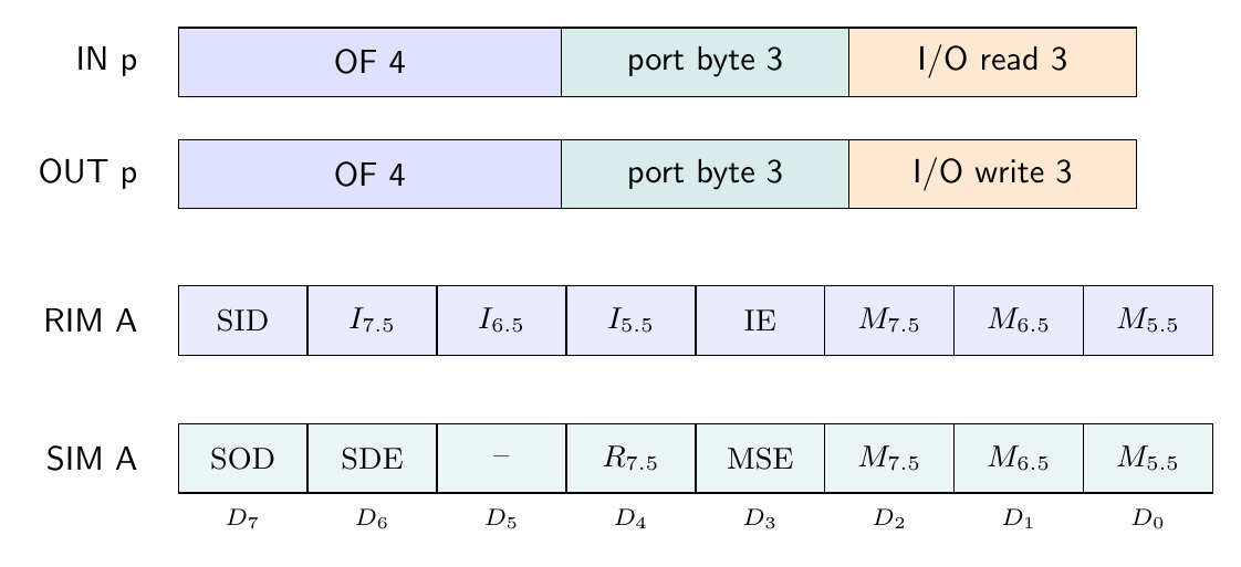
IN port8 (DBH) reads one byte from a selected port into A; OUT port8 (D3H) writes A to a selected port. Each is 2 bytes, 3 machine cycles and 10 T-states: opcode fetch, memory read of the port byte, then I/O read or I/O write. Neither instruction changes the flags.
During the I/O cycle, IO/M=1, and Intel specifies that the eight-bit port number is duplicated on the address bus. IN 05H therefore presents 0505H. The port space contains 256 numbers, but several numbers may be decoded by the same device if the external hardware intentionally ignores some address bits.
An input byte does not automatically establish S,Z,P. For example, IN 20H can load 00H into A while leaving Z=0 from an earlier operation. If the program must branch on the input value, it must execute an appropriate flag-setting instruction such as ORA A or compare against a constant before JZ.
NOP and HLT
NOP (00H) performs no operation, changes no flag, and advances normally after 1 byte, 1 machine cycle and 4 T-states. It is useful as an instruction-stream filler or as a calibrated four-state component of a delay when clock and branch-path timing are fully accounted for.
HLT (76H) is 1 byte, 1 machine cycle and 5 T-states on the 8085. At completion, the PC already contains the next sequential address; registers and flags remain unchanged. An interrupt or reset can restart the processor. If interrupts are disabled, TRAP remains recognizable; otherwise reset is required. The processor may temporarily service a hold request for direct memory access and then re-enter halt.
DI, EI, RIM and SIM
DI (F3H) disables the maskable interrupt system immediately after execution. EI (FBH) enables it only following execution of the next program instruction. The one-instruction delay permits a returning interrupt routine to execute the instruction after EI, commonly RET, before another maskable interrupt is accepted. TRAP cannot be disabled. Intel also states that no interrupt, including TRAP, interrupts execution of DI or EI itself. Both are 1 byte, 1 cycle and 4 T-states and affect no flags.
RIM (20H) transfers interrupt and serial status to the accumulator:
The I bits report pending restart requests, IE reports the global interrupt-enable state, and a mask bit of one means masked. SIM (30H) interprets accumulator bits as
SDE=1 enables transfer of bit 7 to SOD; MSE=1 enables changing the three masks; $R_{7.5}=1$ resets the pending RST 7.5 flip-flop. DI overrides the mask configuration. Each of RIM and SIM is 1 byte, 1 cycle and 4 T-states and affects no condition flag, although RIM necessarily replaces the accumulator.
A path-dependent timing example
Consider a loop with 28 T-states of useful work per iteration, followed by DCR C and JNZ LOOP. DCR C takes 4 T-states and preserves CY. For the first $N-1$ iterations, JNZ is taken and costs 10 T-states; on the final iteration it is not taken and costs 7. Excluding setup, the total is
At $3\,\text{MHz}$ and $N=100$, this is 4197 T-states or $1.399\,\text{ms}$. Replacing the final branch by a fixed ten-state assumption would overcount three T-states. Calls and returns require the same taken/not-taken accounting when they are conditional.
The instruction semantics, opcodes and state counts above follow Intel’s 8080/8085 Assembly Language Programming Manual (November 1978); bus and interrupt signal meanings follow Intel’s MCS-80 User’s Manual (October 1977).
Preparation questions
- Construct the opcodes of
JM,CNCandRPEfrom the common condition field. - Encode
JZ 28A0Hin memory and trace the PC for both flag outcomes. - A
CALLat2000Hbegins withSP=4000H. Identify the return address, final SP and the two stack locations written. - Derive the opcode and target address of
RST 6, and distinguish it from theRST 6.5hardware vector. - Explain why
IN 20Hfollowed immediately byJZdoes not necessarily test whether the input byte is zero. - Compare the false and true timing paths of conditional jump, call and return instructions.
- Decode accumulator value
C9Has aSIMcontrol word, stating which fields are effective.


Discussion