

15 May 2025
8085 Data-Transfer Instruction Set
Register, immediate, indirect, direct and stack-related transfers with opcode fields, little-endian object bytes and exact 8085 timings.
Data-transfer instructions copy bytes or 16-bit quantities among registers, memory, the stack pointer and the accumulator. A copy leaves the source unchanged unless the instruction explicitly describes an exchange. None of the transfer instructions in this lecture alters the condition flags. That property is important: an address can be loaded or a result stored between an arithmetic instruction and a conditional branch without destroying the tested flag state.
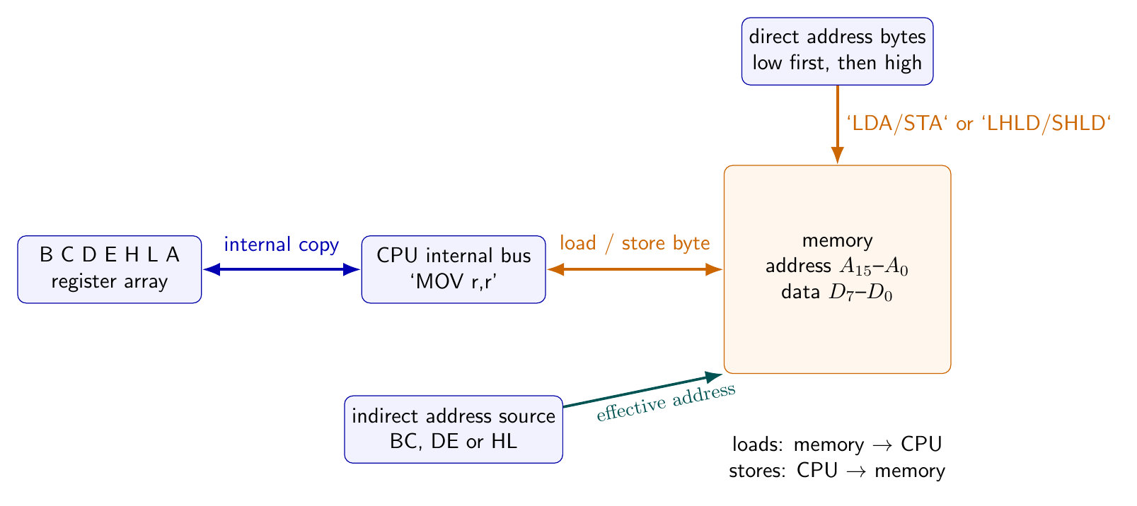
The operand notation M is not an eighth physical 8-bit register. It means the memory byte whose address is in HL:
Consequently, selecting M introduces a memory bus cycle, whereas selecting B,C,D,E,H,L or A usually keeps the transfer inside the CPU.
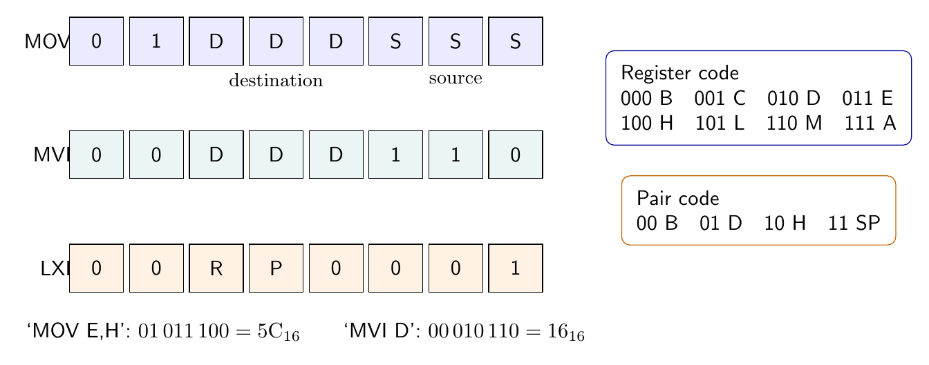
Register codes and the MOV family
Intel assigns three-bit codes
| Operand | B | C | D | E | H | L | M | A |
|---|---|---|---|---|---|---|---|---|
| Code | 000 | 001 | 010 | 011 | 100 | 101 | 110 | 111 |
The MOV opcode is
with destination field DDD and source field SSS. For MOV E,H, DDD=011 and SSS=100, so
For MOV M,A, the fields are 110 and 111, giving 77H; the accumulator is written to memory at HL. For MOV A,M, the fields give 7EH, and the addressed memory byte is read into A. The apparent combination MOV M,M would be 76H, but Intel assigns 76H to HLT; there is no memory-to-same-memory MOV instruction.
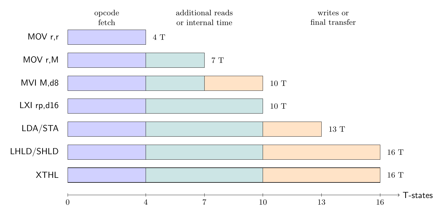
Register-to-register MOV is 1 byte, 1 machine cycle and 4 T-states. A MOV with exactly one M operand is still 1 byte, but it is 2 machine cycles and 7 T-states: opcode fetch plus memory read or memory write. All forms leave S,Z,AC,P,CY unchanged.
Immediate transfers: MVI and LXI
MVI destination,data8 has opcode form
Thus MVI D,7AH has DDD=010 and object bytes 16 7A. With a register destination it uses 2 bytes, 2 machine cycles and 7 T-states. MVI M,7AH is 36 7A; after opcode fetch and immediate-byte read, the processor performs a memory write at HL. It uses 2 bytes, 3 cycles and 10 T-states. Neither form sets flags according to the value loaded.
LXI rp,data16 loads one of BC,DE,HL,SP. The pair codes 00,01,10,11 select B,D,H,SP, and the opcode form is
LXI SP,3FF0H therefore begins with 31H. The 16-bit value is stored low byte first, giving the complete object sequence
31 F0 3F
All LXI forms are 3 bytes, 3 machine cycles and 10 T-states: a four-state opcode fetch and two three-state memory reads. The low byte goes to the low member of a register pair (C,E,L) or the low half of SP; the following byte goes to the high half.
Indirect accumulator transfers
LDAX B and LDAX D load the accumulator from the memory address in BC or DE; their opcodes are 0AH and 1AH. STAX B and STAX D store the accumulator at the address in BC or DE; their opcodes are 02H and 12H. These are the only permitted register-pair operands for LDAX and STAX: LDAX H is not an 8085 instruction. The HL-indirect equivalents are expressed as MOV A,M and MOV M,A.
Every LDAX or STAX is 1 byte, 2 machine cycles and 7 T-states. After the opcode fetch, the second cycle uses the selected pair as the memory address and reads or writes one byte. For example, with D=24H, E=80H and memory 2480H=5AH, LDAX D produces A=5AH; DE, memory and every condition flag are unchanged.
Direct accumulator and HL transfers
LDA address and STA address contain a complete 16-bit memory address. Their fixed opcodes are 3AH and 32H. Thus LDA 2450H is
3A 50 24
The processor fetches the opcode, reads the low and high address bytes, and finally reads memory 2450H into A. STA 2450H, encoded 32 50 24, substitutes a final write of A. Each instruction is 3 bytes, 4 machine cycles and 13 T-states.
LHLD address and SHLD address directly transfer the HL pair using two adjacent memory locations. LHLD 2500H (2A 00 25) performs
SHLD 2500H (22 00 25) stores L at 2500H and H at 2501H. Each is 3 bytes, 5 machine cycles and 16 T-states: opcode fetch, two instruction-byte reads, and two data reads or writes. The address increment from 2500H to 2501H is internal; HL is the transferred data, not the effective address.
Direct and indirect forms support different code-density choices. Once HL already contains an address, MOV A,M is only 1 byte and 7 T-states; LDA address is 3 bytes and 13 T-states. But establishing HL with LXI H,address costs 3 bytes and 10 T-states. Repeated nearby accesses can amortize that setup, whereas one isolated access may be clearer with LDA or STA.
Exchanges and special 16-bit transfers
XCHG (EBH) exchanges HL and DE internally:
It is 1 byte, 1 cycle and 4 T-states. Neither memory nor flags are touched.
XTHL (E3H) exchanges L with memory at SP and H with memory at SP+1. The stack pointer itself is unchanged. It is 1 byte, 5 machine cycles and 16 T-states because the opcode fetch is followed by two stack reads and two stack writes. If initially SP=3000H, HL=1234H, [3000H]=78H and [3001H]=56H, then afterward HL=5678H, [3000H]=34H, [3001H]=12H, and SP=3000H.
SPHL (F9H) copies HL to the stack pointer. It is 1 byte, 1 machine cycle and 6 T-states. PCHL (E9H) copies HL to the program counter, also in 1 byte, 1 cycle and 6 T-states; because the destination is PC, the next opcode fetch comes from the new address and the instruction functions as an indirect jump. Both leave flags unchanged.
Complete timing distinctions
| Group | Instructions | Bytes | Machine cycles | 8085 T-states |
|---|---|---|---|---|
| internal register copy | MOV r1,r2 |
1 | 1 | 4 |
| indirect byte copy | MOV r,M, MOV M,r, LDAX, STAX |
1 | 2 | 7 |
| immediate to register | MVI r,d8 |
2 | 2 | 7 |
| immediate to memory | MVI M,d8 |
2 | 3 | 10 |
| load pair immediate | LXI rp,d16 |
3 | 3 | 10 |
| direct accumulator | LDA, STA |
3 | 4 | 13 |
| direct HL pair | LHLD, SHLD |
3 | 5 | 16 |
| internal exchange | XCHG |
1 | 1 | 4 |
| stack-top exchange | XTHL |
1 | 5 | 16 |
| special pair copy | SPHL, PCHL |
1 | 1 | 6 |
In this table r excludes M and rp denotes an allowed register pair. Byte count is fixed by the assembled instruction. T-state count is the Intel basic count and excludes any READY-generated waits.
The opcode, operation and timing facts follow Intel’s 8080/8085 Assembly Language Programming Manual (November 1978); bus meanings follow Intel’s MCS-80 User’s Manual (October 1977).
Preparation questions
- Construct the opcode of
MOV L,Band state its byte, machine-cycle and T-state counts. - Explain why opcode
76Hcannot be interpreted asMOV M,M. - Assemble
LXI D,48A2Hbyte by byte and identify which byte entersEfirst. - Compare the timing and code size of
LDA 2800HwithMOV A,MwhenHL=2800His already available. - Trace every memory read and write performed by
SHLD 30FFH. - Given the initial state in the
XTHLexample, verify the final four bytes/register values without changingSPor flags. - Why are
LDAX HandSTAX SPinvalid even thoughHandSPare legalLXIoperands?


Discussion