

11 May 2025
8085 Fetch-Decode-Execute Sequence and Machine Cycles
Instruction sequencing from opcode fetch through execution, with byte order, machine-cycle decomposition and exact 8085 T-state counts.
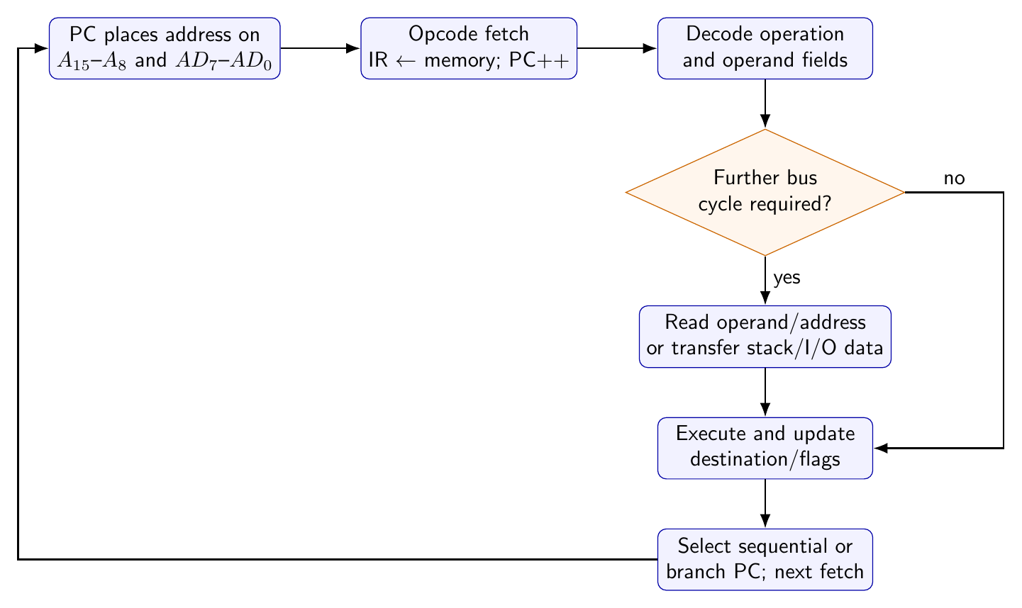
An 8085 instruction is not completed in one indivisible event. It is an ordered sequence of bus transfers and internal operations. The processor first places the program-counter address on the bus, reads the opcode, decodes the bit pattern, obtains any further operand bytes, performs the specified data transfers or arithmetic, and establishes the address of the next instruction. The useful hierarchy is
\[\boxed{\text{program}\supset\text{instruction cycle} \supset\text{machine cycle}\supset\text{T-state}}.\]A T-state is one processor clock period. A machine cycle is one elementary processor activity, normally one bus transaction such as opcode fetch, memory read or memory write. An instruction cycle contains every machine cycle needed to complete one instruction. Wait states inserted for a slow memory or peripheral enlarge a machine cycle but do not add an instruction byte.

The first machine cycle: opcode fetch
At the start of an instruction, the program counter (PC) contains the address of its first byte. During $T_1$ of the opcode-fetch cycle the 8085 drives the high-order address on $A_{15}$-$A_8$ and the low-order address on multiplexed lines $AD_7$-$AD_0$. ALE marks the address phase so that external hardware can latch $A_7$-$A_0$. In the following bus phase the same $AD$ lines become the data bus. With $\overline{\mathrm{RD}}$ active, memory supplies the opcode; the processor loads it into the instruction register and advances the PC.
The ordinary 8085 opcode fetch occupies four T-states. Its first three states carry the address and opcode transfer; $T_4$ is available for decode and internal action. Thus a register-to-register instruction such as MOV B,C is one byte, one machine cycle and four T-states. Its opcode is 41H, and no additional memory access is required because both operands are already inside the CPU.
Decode interprets fields rather than merely looking up 256 unrelated commands. For MOV, the form is
where 000,001,010,011,100,101,110,111 select B,C,D,E,H,L,M,A, respectively, and M denotes the memory byte addressed by HL. Therefore MOV A,M is
The decoder sees both the operation group and the operand fields. Because the source code is 110, it schedules a second machine cycle to read memory at the address in HL; MOV A,M therefore takes two machine cycles and seven T-states, not four.
Instruction bytes and little-endian order
The byte count specifies storage, whereas the T-state count specifies basic execution time; they must not be confused. A one-byte instruction contains only its opcode. A two-byte instruction contains an opcode followed by one immediate data or port byte. A three-byte instruction contains an opcode followed by a 16-bit quantity in low-byte, high-byte order.
For example, suppose location 2000H contains
2000: 21
2001: 50
2002: 20
The sequence is LXI H,2050H. 21H is fetched in the four-state opcode-fetch cycle. Two three-state memory-read cycles then obtain 50H and 20H. The low byte enters L, the high byte enters H, and the completed instruction occupies 3 bytes, 3 machine cycles and 10 T-states. The PC has advanced from 2000H to 2003H.
The same byte ordering applies to direct addresses. LDA 3050H is assembled as 3A 50 30. Its operation is longer than LXI: after fetching all three instruction bytes, it must perform a fourth machine cycle to read the data byte at 3050H. Consequently LDA is 3 bytes, 4 machine cycles and 13 T-states.
Representative cycle decompositions
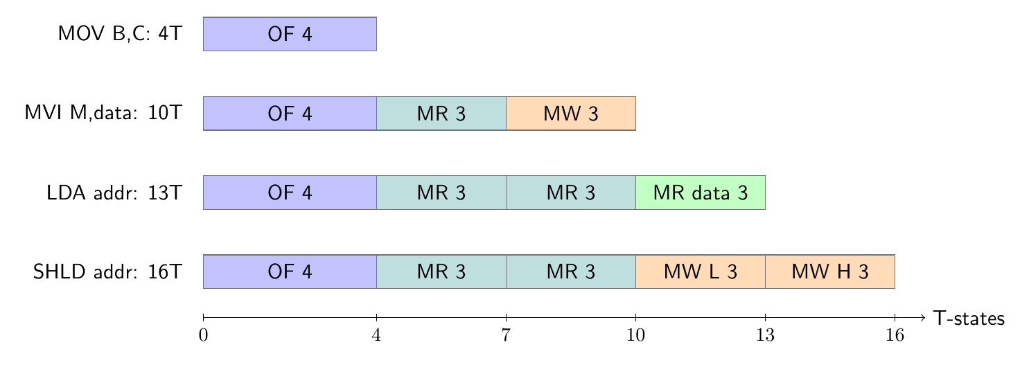
The following decompositions make the source of each timing count explicit. OF denotes a four-state opcode fetch; MR and MW denote three-state memory read and write cycles.
| Instruction | Bytes | Machine-cycle sequence | Cycles | T-states | Flags |
|---|---|---|---|---|---|
MOV B,C |
1 | OF | 1 | 4 | none |
MOV A,M |
1 | OF + MR at HL |
2 | 7 | none |
MVI D,7AH |
2 | OF + MR immediate | 2 | 7 | none |
LXI H,2050H |
3 | OF + MR low + MR high | 3 | 10 | none |
MVI M,32H |
2 | OF + MR immediate + MW at HL |
3 | 10 | none |
LDA 3050H |
3 | OF + MR low + MR high + MR data | 4 | 13 | none |
STA 3050H |
3 | OF + MR low + MR high + MW data | 4 | 13 | none |
LHLD 3050H |
3 | OF + two address reads + two data reads | 5 | 16 | none |
SHLD 3050H |
3 | OF + two address reads + two data writes | 5 | 16 | none |
LHLD 3050H reads memory 3050H into L and 3051H into H. SHLD performs the inverse pair of writes. The five cycles total $4+3+3+3+3=16$ T-states. This is a useful check against the common error of counting the 16-bit transfer as one memory access.
Internal execution states
Not every T-state corresponds to a new external memory byte. INX H and DCX H are one-byte instructions that require six T-states on the 8085. They fetch one opcode, then use additional internal time to change the 16-bit register pair; no operand byte is fetched. PCHL and SPHL likewise require one machine cycle and six T-states. DAD B, which adds BC to HL, takes three cycles and ten T-states while affecting only CY; the extra activity is internal rather than three independent instruction bytes.
This distinction is why a byte-count rule cannot predict execution time. XCHG exchanges DE and HL in one byte and four T-states, while the equally short XTHL exchanges HL with two stack bytes and takes five machine cycles and sixteen T-states. The latter requires two stack reads and two stack writes after opcode fetch.
Program-counter evolution and branch timing
Normally the PC increments after each instruction-byte fetch, so after an $n$-byte sequential instruction it points to the first byte that follows. A branch replaces this sequential value when its condition is satisfied. This changes timing on the 8085.
An unconditional JMP 2050H is C3 50 20, three bytes, three machine cycles and ten T-states. For a conditional jump such as JNZ 2050H, the 8085 uses two cycles and seven T-states when the condition is false, but three cycles and ten T-states when it is true. Intel specifies the reason: the 8085 fetches the third instruction byte only when the destination is actually needed. In either case the instruction has a three-byte encoding in memory; the variable is which bytes are fetched during that execution path.
Conditional calls separate storage length from timing even more sharply. CNZ 2050H occupies three bytes. If Z=1, the not-taken path uses two machine cycles and nine T-states. If Z=0, the taken path fetches the target and pushes the return PC in five machine cycles and eighteen T-states. A conditional return occupies one byte yet takes one cycle and six T-states when not taken, or three cycles and twelve T-states when taken because the return address must be popped.
Timing calculations and wait states
If the processor clock period is $T_{\mathrm{clk}}$, the no-wait execution time is
\[t_{\mathrm{instruction}}=N_TT_{\mathrm{clk}} =\frac{N_T}{f_{\mathrm{clk}}}.\]At $3.000\,\text{MHz}$, one T-state is $333.333\,\text{ns}$. LDA therefore requires
while the taken and not-taken paths of JNZ require $3.333\,\mu\text{s}$ and $2.333\,\mu\text{s}$, respectively. These are basic values. If READY is low, the CPU inserts one or more wait states into the affected read or write cycle. With $N_W$ wait states,
For LDA, two waits in the final data-read cycle change the count from 13 to 15 T-states, or $5.000\,\mu\text{s}$ at $3\,\text{MHz}$. Wait states change elapsed time but neither the opcode nor the architectural result.
The timing and instruction facts above follow Intel’s MCS-80 User’s Manual (October 1977) and 8080/8085 Assembly Language Programming Manual (November 1978).
Preparation questions
- Separate the instruction cycle of
MVI M,32Hinto machine cycles and account for all ten T-states. - Construct the opcode for
MOV D,Afrom01 DDD SSS, and state its byte, cycle and T-state counts. - Memory beginning at
2400Hcontains2A 80 31. Trace the PC and every memory address read by this instruction. - Explain why
XTHLandXCHGhave the same byte count but different machine-cycle counts. - At $2.5\,\text{MHz}$, calculate the taken and not-taken execution times of
JNZwith no wait states. - An
LDAexecution contains three inserted waits. Find its total T-state count and distinguish this from its three-byte length. - Why can an additional internal T-state occur without an additional instruction byte or external memory access?


Discussion