

09 May 2025
8085 Instruction Word Size and Addressing Modes
One-, two- and three-byte 8085 instructions, little-endian operands, effective addresses and the complete addressing-mode framework.
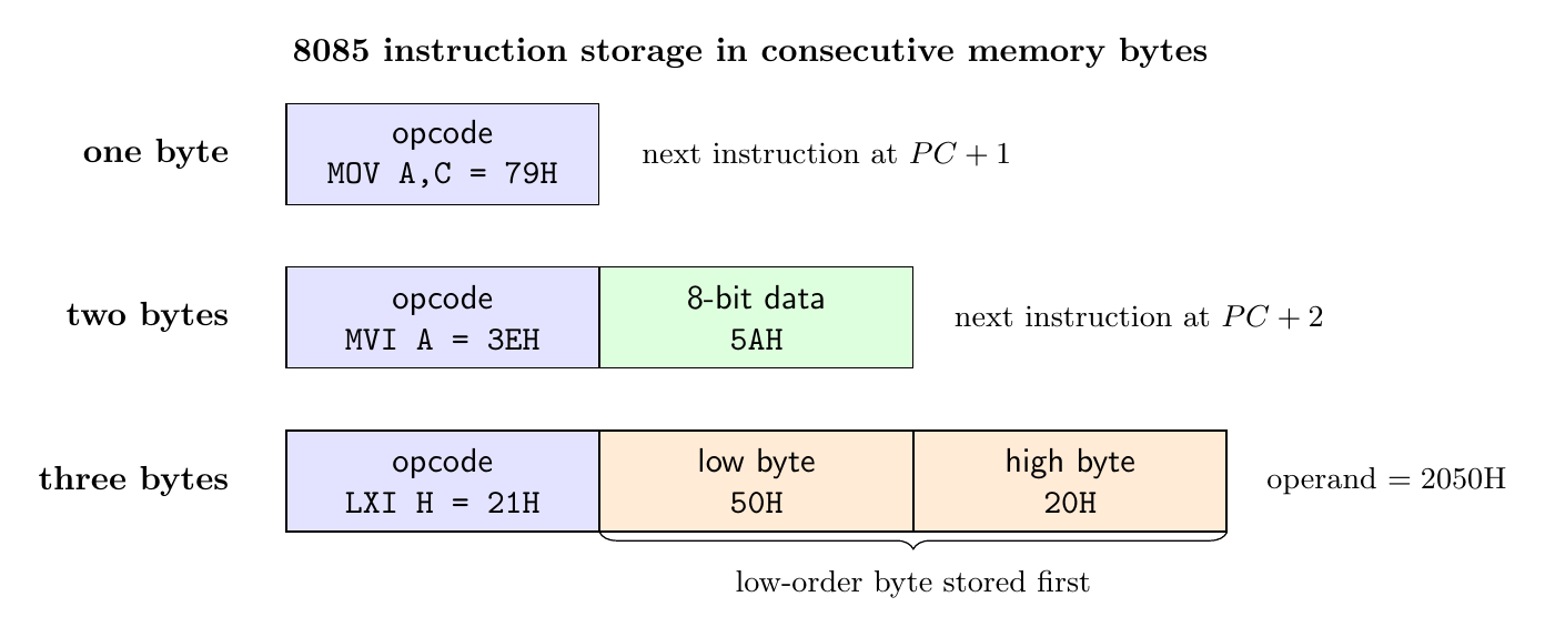
An 8085 instruction occupies one, two, or three consecutive memory bytes. Its first byte is always the opcode; any following bytes carry immediate data, a port number, or a 16-bit address. This stored length is the instruction size. It is not the number of machine cycles, the number of clock states, or the width of the external address bus.
The 8085 is an 8-bit processor because its principal data path and accumulator operate on 8-bit quantities. It nevertheless has a 16-bit program counter, stack pointer, and address space. Consequently, “word” is potentially ambiguous: an 8085 data word is normally one byte, a memory address is two bytes, and an instruction word may contain one to three bytes. State the intended meaning whenever the distinction matters.
The classification and terminology below follow Intel’s 8080/8085 Assembly Language Programming Manual. The complementary hardware context is in Intel’s MCS-80 User’s Manual.
One-byte instructions
A one-byte instruction places all explicitly encoded information in the opcode byte. It may have no written operand, as in CMA, or it may encode one or two registers in bit fields, as in ADD D and MOV A,C.
Examples are
| Assembly instruction | Machine byte | Meaning |
|---|---|---|
CMA |
2FH |
Complement the accumulator; the accumulator is implied |
ADD D |
82H |
Add register D to A |
MOV A,C |
79H |
Copy C into A |
MOV A,M |
7EH |
Read the byte at the address in HL into A |
PCHL |
E9H |
Copy HL into the program counter |
The last two examples expose an essential point. One byte of instruction storage does not mean that execution uses only internal registers. MOV A,M has its complete specification in the opcode, yet it needs a separate memory-read machine cycle because M denotes the memory byte addressed by HL. PCHL is also one byte even though it changes a 16-bit register, because both the source and destination are implied by the opcode.
Two-byte instructions
A two-byte instruction has one opcode byte followed by one operand byte. The second byte can be an 8-bit constant or an 8-bit I/O port address.
For example,
MVI A,5AH       3E 5A
ADI 24H         C6 24
IN 80H          DB 80
OUT 21H         D3 21
If MVI A,5AH begins at address 2000H, the opcode 3EH is at 2000H, the immediate byte 5AH is at 2001H, and the next instruction begins at 2002H. The program counter advances after each fetch, so it points to the next instruction after the second byte has been read.
The second byte of IN 80H is not data to be loaded into A. It selects I/O port 80H; the actual input byte is obtained during a later I/O-read machine cycle. Thus equal instruction length does not imply equal operand meaning or equal bus activity.
Three-byte instructions and byte order
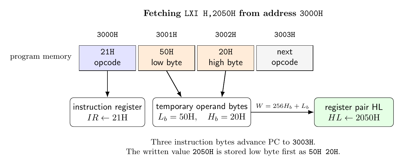
A three-byte instruction contains an opcode followed by a 16-bit quantity. The 8085 stores the low-order byte first and the high-order byte second:
\[W=256H+L,\]where $L$ is the byte at address $PC+1$ and $H$ is the byte at $PC+2$. This is little-endian order for an immediate word or a direct address.
LXI H,2050H     21 50 20
LDA 2500H       3A 00 25
JMP 1234H       C3 34 12
CALL 4080H      CD 80 40
For JMP 1234H, the processor reads C3H, then 34H, then 12H, reconstructs $12_{16}\times100_{16}+34_{16}=1234_{16}$, and loads that value into PC. The low-byte-first rule is about storage order; the written hexadecimal address retains its usual high-to-low notation.
Addressing mode as an effective-address rule
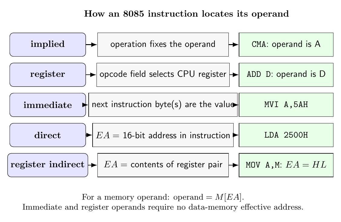
An addressing mode states how an instruction identifies its operand. A useful formal description is
\[\text{operand}=M[EA],\]when the operand is in memory, where $EA$ is the effective address. For a register or an immediate instruction no data-memory effective address is required. The mode is an interpretation rule, not merely the visible punctuation of the assembly statement.
Intel groups the basic forms as implied, register, immediate, direct, and register indirect addressing, with some instructions combining modes.
Implied addressing
In implied addressing the operation itself fixes the operand, so no operand field is permitted. CMA acts on A, RAL rotates A through carry, STC sets carry, XCHG exchanges DE with HL, and RIM reads interrupt-mask and serial-input status into A. The absence of a written operand does not mean absence of data; it means that no choice of operand remains for the programmer.
Stack and return operations can also contain implicit resources. RET obtains a new program counter from the memory stack addressed by SP. Intel therefore describes some operations in terms of implied or register-indirect behavior depending on whether the programmer’s notation or the complete hardware action is being emphasized.
Register addressing
In register addressing an operand is in a named CPU register. Examples include MOV D,E, INR H, SUB B, and CMP L. Register access normally avoids an extra data-memory cycle. In MOV D,E, the destination and source fields are both embedded in the opcode 53H:
with destination code 010 for D and source code 011 for E.
Register-pair instructions use BC, DE, HL, or SP as a 16-bit unit. INX H increments HL, while DAD B adds BC to HL. PSW is a special stack-pair name for the accumulator and flags; it is not a general 16-bit arithmetic register.
Immediate addressing
In immediate addressing the constant is part of the instruction stream. MVI C,7FH supplies an 8-bit value, ADI 09H supplies an 8-bit addend, and LXI SP,30FFH supplies a 16-bit value. The processor reads the constant from memory locations following the opcode, but those bytes are program data embedded in the instruction, not data-memory addresses.
This distinction resolves a common error: LXI H,2500H loads the numerical value 2500H into HL; it does not read the contents of memory location 2500H. Afterward, MOV A,M would use HL indirectly and read that location.
Direct addressing
In direct addressing the instruction contains the address needed by the operation. For LDA 2500H,
STA, LHLD, and SHLD similarly contain direct memory addresses. Jumps, calls, and conditional branches contain the direct destination that can replace PC. The encoding occupies three bytes because the address is 16 bits.
LHLD 2500H reads two adjacent bytes: $L\leftarrow M[2500H]$ and $H\leftarrow M[2501H]$. SHLD performs the inverse writes. The order reflects the convention that the low byte of a 16-bit quantity resides at the lower memory address.
Register-indirect addressing
Here a register pair holds the effective address. MOV A,M means $A\leftarrow M[HL]$, and MOV M,C means $M[HL]\leftarrow C$. LDAX B uses BC as the address; LDAX D uses DE. Their store counterparts are STAX B and STAX D. The assembler symbol M is not a physical register and does not contain data independently of memory.
Register-indirect addressing is compact: the address does not occupy instruction bytes and can be advanced in a loop. A byte-copy loop can increment HL and DE after each transfer rather than rebuild two direct addresses in every instruction.
Combined modes, I/O addressing and stack effects
Some instructions perform more than one addressing action. CALL 4080H obtains its branch destination directly from the instruction, but it stores the return address indirectly through SP. The 8085 first forms the return address of the next instruction, decrements SP, and writes the two return bytes to the stack before placing 4080H in PC. RET reverses the transfer through the stack.
IN port and OUT port carry an 8-bit port number in the second byte. They are immediate with respect to the encoded port selector, while the actual data transfer occurs in I/O space. Because the 8085 exposes an 8-bit port field, these instructions directly select 256 port numbers from 00H through FFH. Memory-mapped I/O, by contrast, uses ordinary memory instructions and one of the memory addressing modes.
Instruction length is independent of execution cost
An instruction fetch is a machine cycle, but further cycles depend on the action. MOV B,C is one byte and needs no external operand transfer. MOV B,M is also one byte but requires a memory read. MVI M,5AH occupies two bytes and needs both the immediate-byte read and a memory write through HL. LDA 2500H occupies three bytes and performs a separate data read after fetching its address bytes. CALL adds stack writes, and a conditional call may have different timing depending on whether the condition is true.
Therefore, never infer timing from byte length alone. Keep three quantities separate:
\[\text{instruction bytes},\qquad \text{machine cycles},\qquad \text{T-states}.\]The program counter advances by the stored instruction length during sequential fetch. Memory and I/O transactions performed by execution do not add to that length. This separation allows exact program layout, bus analysis, and timing analysis to be done without mixing distinct architectural ideas.
Preparation questions
- Distinguish processor word size, address width, instruction length, machine cycles, and T-states for the 8085.
- Place the bytes of
LXI D,4A20Hin memory beginning at3000H, and give the address of the next instruction. - Explain why
MOV A,Mis a one-byte instruction but normally requires a data-memory read. - For each of
CMA,MOV B,E,MVI B,7FH,LDA 2400H, andSTAX D, identify the addressing mode and source of the operand. - Compare
LXI H,2500HwithLHLD 2500H; state exactly what value or bytes each instruction transfers. - Explain why
CALLis naturally described as combining direct and register-indirect addressing. - Encode the 16-bit operand bytes of
JMP 8C35Hand explain their order in memory.


Discussion