

25 May 2025
8085 Interrupt System: Hardware Requests, Vectors, SIM and RIM
Interrupt recognition, priority and trigger modes, vectored and non-vectored response, interrupt masking, context preservation and controlled nesting.
An interrupt is an event that requests a temporary transfer of control from the foreground program to an interrupt-service routine (ISR). Unlike a subroutine call, the transfer is initiated by an event rather than by a CALL written at the point of transfer. The 8085 nevertheless uses the same descending stack to preserve the return address.
Interrupt response is an instruction-boundary operation. The processor completes the instruction in progress, samples eligible requests, resolves simultaneous requests by fixed priority and, if a request is accepted, saves the address of the next foreground instruction. The programmer must distinguish three independent ideas:
- enable state—the global interrupt-enable flip-flop controlled by
EIandDI; - mask state—the individual masks for
RST 5.5,RST 6.5andRST 7.5; - request state—the electrical level or latched edge indicating that a device requires service.
A request is serviceable only when its recognition conditions are satisfied. TRAP is the exceptional non-maskable input.
Interrupt inputs, priority and vectors
The five hardware request inputs have the following properties. A vector is the address loaded into the program counter without requiring the external device to supply that address.
| Input | Priority | Maskability | Request sensing | Vector |
|---|---|---|---|---|
TRAP |
1, highest | non-maskable | edge-and-level qualified | $0024_H$ |
RST 7.5 |
2 | individually maskable | positive edge, internally latched | $003C_H$ |
RST 6.5 |
3 | individually maskable | level sensitive | $0034_H$ |
RST 5.5 |
4 | individually maskable | level sensitive | $002C_H$ |
INTR |
5, lowest | globally maskable | level sensitive | non-vectored |
The fractional restart names describe vectors halfway between the ordinary software-restart vectors. For example,
\[8(5.5)=44_{10}=2C_H,\qquad 8(6.5)=52_{10}=34_H,\qquad 8(7.5)=60_{10}=3C_H.\]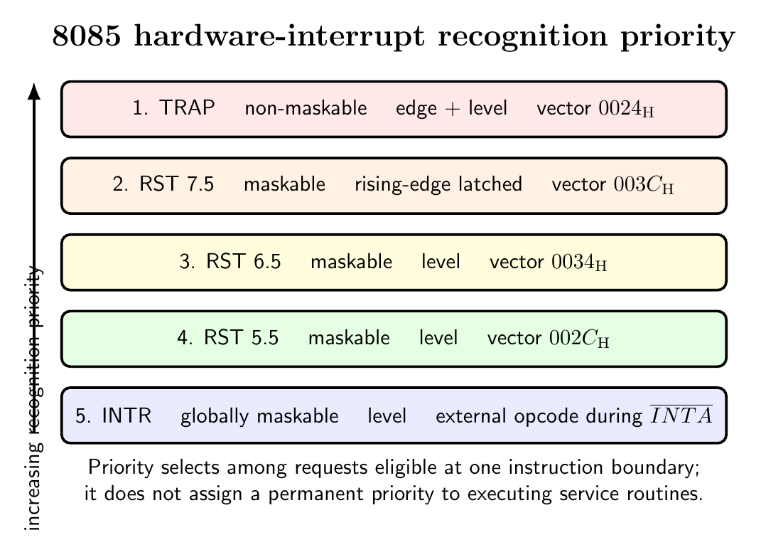
On accepting a vectored request, the processor pushes the current program counter and loads the appropriate vector. Because the neighbouring software and hardware vectors can be only four bytes apart, a vector location normally contains a three-byte jump to the full ISR:
        ORG 003CH
        JMP ISR75       ; complete instruction fits in the vector slot
The restart vectors must be reserved consistently; they are not ordinary data storage once interrupts are in use.
Trigger modes and pending requests
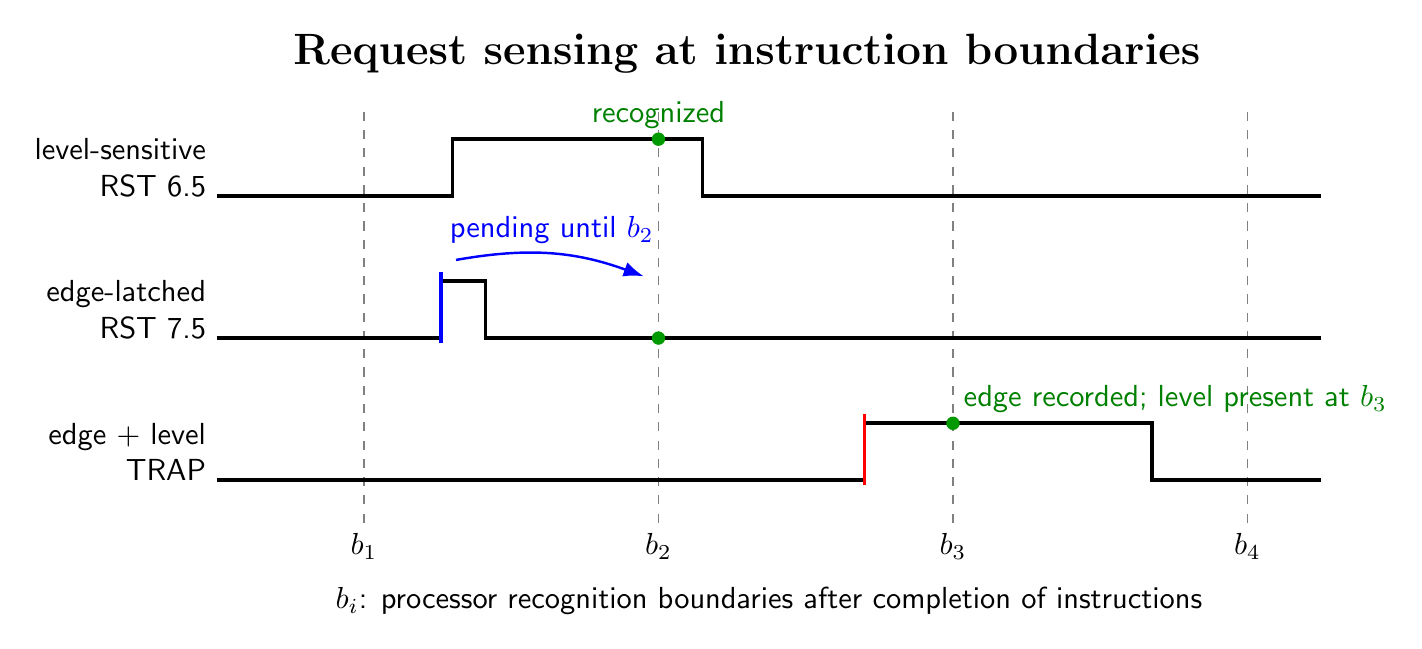
RST 5.5, RST 6.5 and INTR are level-sensitive. A device must keep such a request asserted until the processor recognizes it. If the level disappears before a recognition boundary, there need not be any record of it. The device should remove the request according to its interface handshake so that the same level is not accepted repeatedly after interrupts are enabled again.
RST 7.5 is rising-edge sensitive and its request is stored in an internal flip-flop. A short positive pulse can therefore remain pending after the pin returns low. The latch is cleared when the request is accepted, when the processor is reset, or when bit 4 of an accumulator pattern is acted upon by SIM. Masking RST 7.5 prevents recognition but does not prevent a new edge from setting its pending latch.
TRAP is both edge- and level-qualified: the edge records the event, while the asserted level must satisfy the recognition requirement. It cannot be disabled by DI or by a SIM mask. This makes it suitable for exceptional conditions such as power failure, but it also means that a valid vector routine must always be present if the pin can be activated.
Priority operates only when the processor chooses among eligible requests. Once an ISR has started, it has no intrinsic hardware rank. Acceptance clears the global enable state for maskable interrupts. Consequently, the ISR will run without maskable nesting unless it deliberately executes EI. If it does execute EI, any enabled request—including one nominally lower in the fixed input priority—may interrupt it at a later instruction boundary.
Non-vectored INTR and interrupt acknowledge
INTR does not have an internal restart vector. When it is accepted, the processor asserts the active-low interrupt-acknowledge signal, $\overline{INTA}$, in place of an ordinary opcode memory read. External interrupt hardware must place an instruction opcode on the data bus. A one-byte RST n is the usual response because it supplies an eight-byte-spaced vector in a single opcode:
For example, external delivery of $EF_H=RST\ 5$ transfers control to $0028_H$. A priority encoder or interrupt controller can use the acknowledge cycle to select which device supplies the opcode. The request source must keep INTR valid until acknowledgment. Supplying a multi-byte instruction demands additional external support for its following bytes, so the self-contained one-byte restart response is the robust interface.
For any accepted restart-like transfer, the return-address stack action is
\[SP\leftarrow SP-1,\ [SP]\leftarrow PCH;\qquad SP\leftarrow SP-1,\ [SP]\leftarrow PCL;\qquad PC\leftarrow V.\]The flags and general registers are not automatically stacked. Hardware saves only the return address needed by RET.
Global enable and individual masks
DI clears the global interrupt-enable state. EI enables the maskable interrupt system after the instruction following EI has executed. The one-instruction delay permits the standard ISR ending
        EI
        RET
to restore the foreground program before another maskable interrupt is accepted. Reset disables the maskable system. Neither EI nor DI changes the three individual mask bits, and neither makes TRAP maskable.
SIM interprets the accumulator as a control word, whereas RIM returns interrupt and serial-input status in the accumulator.
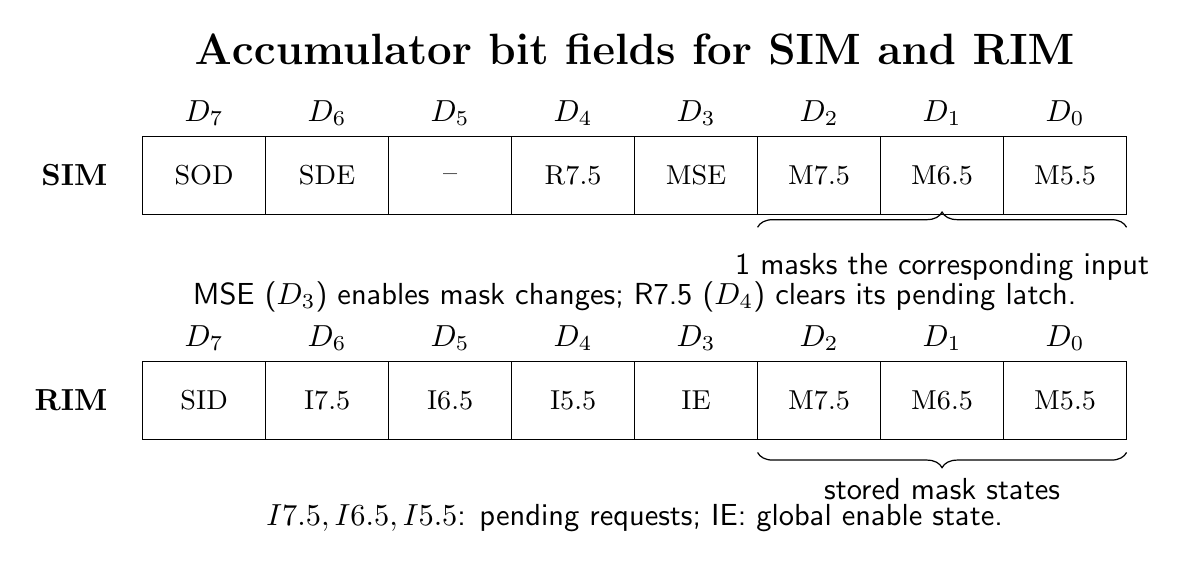
For SIM, bits $D_2,D_1,D_0$ are the masks for $7.5,6.5,5.5$ respectively, with 1 meaning masked. They are applied only when mask-set enable $D_3=1$. Bit $D_4=1$ clears the RST 7.5 pending flip-flop. $D_6$ enables serial output and, when enabled, $D_7$ is latched at SOD; $D_5$ is unused. Thus
        MVI A,0AH       ; 0000 1010: MSE=1, mask 6.5 only
        SIM

        MVI A,10H       ; clear pending 7.5; MSE=0, masks unchanged
        SIM
For RIM, the returned bits are
The pending bits describe the three restart inputs, not TRAP or INTR. The status can be decoded without destroying the original byte by first copying it to another register.
ISR context and nesting discipline
An ISR must preserve every foreground register or flag that it may alter, except values explicitly used to communicate with the foreground task. A conservative ISR skeleton is
ISR75: PUSH PSW
       PUSH B
       PUSH D
       PUSH H
       ; acknowledge or service the device
       ; keep this bounded in execution time
       POP  H
       POP  D
       POP  B
       POP  PSW
       EI
       RET
The device-specific acknowledge should normally occur early enough to remove a level request or clear a peripheral latch. Context must be restored in reverse push order. If an ISR calls an ordinary subroutine, that subroutine’s linkage and register convention still applies inside the interrupt context.
For a foreground maximum call depth $d$, $p$ unmatched pair saves, and at most $q$ simultaneously active ISRs whose saved contexts contain $c_i$ register-pair pushes, a safe lower bound on stack consumption is
\[D_{\rm stack}=2d+2p+\sum_{i=1}^{q}\left(2+2c_i\right).\]The first 2 in each ISR term is the automatically pushed return address. This bound must be increased for subroutine calls made from an ISR and for any explicitly stacked data.
Interrupt latency is similarly compositional. If a request arrives during an instruction requiring $T_r$ remaining clock states, and recognition plus vector transfer requires $T_a$, then the first ISR instruction begins after approximately
\[L=(T_r+T_a)T_{\rm clk}.\]The arrival phase makes $T_r$ variable. Disabling interrupts creates an additional blocking interval, so a real-time design must bound the longest disabled section as well as the longest indivisible instruction.
Intentional nesting should be enabled only after the current ISR has saved context and placed its device in a state safe against repeated service. Software masks may then enforce a policy stronger than the fixed recognition order. Without an explicit policy, nesting makes stack depth and response time difficult to bound.
Preparation questions
- Derive all four internal hardware vectors and explain why some vector stubs have only four available bytes.
- Distinguish the electrical recognition of
RST 6.5,RST 7.5andTRAPusing timing sketches. - Explain the complete
INTR–$\overline{INTA}$ transaction and design an external response that suppliesRST 5. - Construct
SIMcontrol words that (a) mask onlyRST 5.5, (b) unmask all three restart inputs, and (c) clear the pendingRST 7.5latch without changing masks. - Decode every bit of the accumulator after
RIMreturns $ED_H$. - Explain why fixed input priority does not prevent a low-priority ISR from interrupting a high-priority ISR after
EI. - Calculate the stack allocation for three nested calls and two nested ISRs, each saving PSW, BC, DE and HL.
- Write an ISR that increments a 16-bit event counter while preserving foreground state and preventing a torn counter update.


Discussion