

27 May 2025
8085 Machine and Assembly Language Programming
Binary instruction representation, symbolic source programs, canonical two-pass assembly, object generation, relocation and a disciplined edit–assemble–test workflow.
A stored program is ultimately a sequence of bytes interpreted by the processor as opcodes and operands. Machine language exposes those bytes directly. Assembly language replaces numerical opcodes and addresses by mnemonics, symbols and expressions, and delegates their translation to an assembler. Both describe the same 8085 operations; they differ in representation and in the amount of address bookkeeping performed by the programmer.
For example, the instruction
JNZ LOOP
may become the three machine bytes
C2 05 20
when LOOP has address $2005_H$. The first byte is the JNZ opcode. The operand address $2005_H$ is stored in the next two bytes in low-byte-first order, $05_H,20_H$. If the program is moved and the symbol acquires a different address, the assembly source remains meaningful while the numerical operand bytes must change.
Machine-language representation
In machine-language programming, the programmer selects absolute memory addresses and enters hexadecimal or binary bytes. An instruction occupying $n$ bytes advances the location counter by $n$:
\[LC_{i+1}=LC_i+n_i.\]The starting address of every later instruction therefore depends on all earlier instruction lengths. A one-byte insertion can alter every subsequent branch target. Numerical programs are compact for the processor but poor at expressing intent, data structure and linkage.
Consider the following byte sequence beginning at $2000_H$:
| Address | Byte(s) | Decoded instruction |
|---|---|---|
| $2000_H$ | 21 10 20 |
LXI H,2010H |
| $2003_H$ | 06 04 |
MVI B,04H |
| $2005_H$ | 7E |
MOV A,M |
| $2006_H$ | D3 20 |
OUT 20H |
| $2008_H$ | 23 |
INX H |
| $2009_H$ | 05 |
DCR B |
| $200A_H$ | C2 05 20 |
JNZ 2005H |
| $200D_H$ | 76 |
HLT |
The bytes are executable, but the roles of $2010_H$, $04_H$ and $20_H$ are not visible. A transcription error can still produce a legal instruction and hence remain undetected until execution.
Assembly-language source statements
A conventional source statement has four conceptual fields:
label: mnemonic operand(s) ; comment
The label assigns a symbolic name to the current location. The mnemonic selects an operation. Operands identify registers, immediate constants, ports or memory addresses. A comment records an invariant or interface that cannot be inferred from the opcode. Labels such as NEXT, COUNT and RESULT are resolved by the assembler; they do not occupy memory merely because they have names.
Assembler directives control translation but are not processor instructions. Common Intel-style directives include ORG for location-counter placement, EQU for a symbolic constant, DB and DW for byte and word data, DS for reserved storage, and END for the end of a source module. A word created by DW or used as a 16-bit instruction operand follows the target representation; the 8085 reads instruction-address operands low byte first.
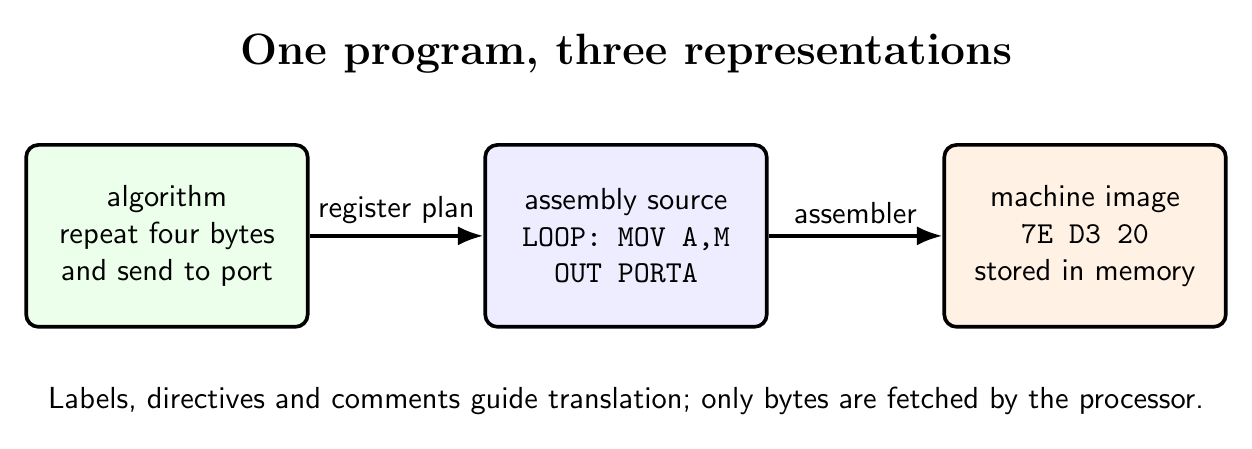
An assembly version of the preceding machine program is
PORTA   EQU 20H
COUNT   EQU 04H

        ORG 2000H
START:  LXI H,SOURCE
        MVI B,COUNT
LOOP:   MOV A,M
        OUT PORTA
        INX H
        DCR B
        JNZ LOOP
        HLT

        ORG 2010H
SOURCE: DB 12H,34H,56H,78H
        END START
The source states that HL is a pointer, B is a count and $20_H$ is an output port. Translation produces exactly the executable bytes shown above, with the four data bytes placed at $2010_H$ through $2013_H$.
Canonical two-pass assembly
Forward references make a single immediate translation inconvenient. In
        JMP INITIALIZE
        ; ...
INITIALIZE: XRA A
the operand of JMP appears before the definition of INITIALIZE. A canonical two-pass assembler separates address assignment from final code emission.
Pass 1: assign locations and construct symbols
Pass 1 initializes the location counter from ORG and processes each source line in order. For an instruction or data directive it determines the required number of bytes and advances $LC$. For a label it enters
in a symbol table. Attributes distinguish absolute constants from addresses that may require relocation. EQU assigns an expression value without reserving a processor instruction. DS n advances the location counter by $n$ without generating initialized data.
The instruction length must be known from the mnemonic and addressing form even when an operand symbol is not yet defined. Thus a forward JMP reserves three bytes during pass 1. Multiple definitions, illegal mnemonics and some range errors can already be reported.
For the example, the important symbol values are
\[PORTA=0020_H,\quad COUNT=0004_H,\quad START=2000_H,\quad LOOP=2005_H,\quad SOURCE=2010_H.\]Pass 2: evaluate operands and emit object code
Pass 2 scans the source again with the completed symbol table. It selects the opcode, evaluates operand expressions, checks their permitted ranges and emits data bytes. For a 16-bit operand $W$,
\[W_L=W\bmod 256,\qquad W_H=\left\lfloor\frac{W}{256}\right\rfloor,\]so JNZ LOOP at $200A_H$ becomes $C2_H,05_H,20_H$. Undefined symbols, invalid register combinations and values outside byte or word range are diagnosed. The assembler can simultaneously produce a listing that places source statements beside assigned addresses and generated bytes, and a cross-reference that lists every definition and use of a symbol.
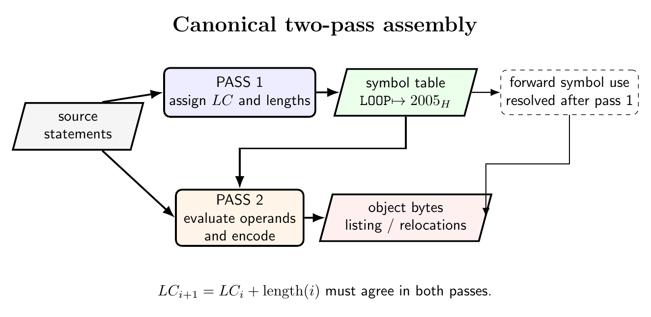
The abstract pass algorithms are
PASS 1
  LC <- initial origin
  for each source statement:
      if label exists: enter(label, LC, attributes)
      if directive: update LC or symbol table
      if instruction: LC <- LC + encoded_length(instruction)

PASS 2
  LC <- initial origin
  for each source statement:
      evaluate operands using symbol table
      emit opcode and operand bytes, or create relocation records
      update LC exactly as in pass 1
The essential consistency condition is that both passes assign the same length to every line. If a pseudo-operation has data-dependent size, its pass-1 size rule must exactly match pass 2.
Absolute and relocatable object code
An absolute assembly fixes all addresses at assembly time and can be loaded only at its assigned locations. A relocatable module leaves selected address fields for later adjustment. The object module then contains generated bytes, symbol definitions, unresolved external references and relocation records identifying address fields that depend on placement.
Suppose a module is assembled relative to zero and contains a word referring to an internal symbol at relative address $r$. If the locator places the module at base $B$, the final value is
\[A=(B+r)\bmod 2^{16}.\]A linker combines modules, matches exported symbols with external references and reports unresolved or multiply defined names. A locator assigns final memory regions and applies relocation. The distinction matters in an 8085 system whose ROM, RAM and peripheral map impose different placement constraints.
Object bytes are commonly transported in records that include an address, byte count and checksum. The checksum detects transmission errors; it does not prove that the program implements the intended algorithm.
Development and verification workflow
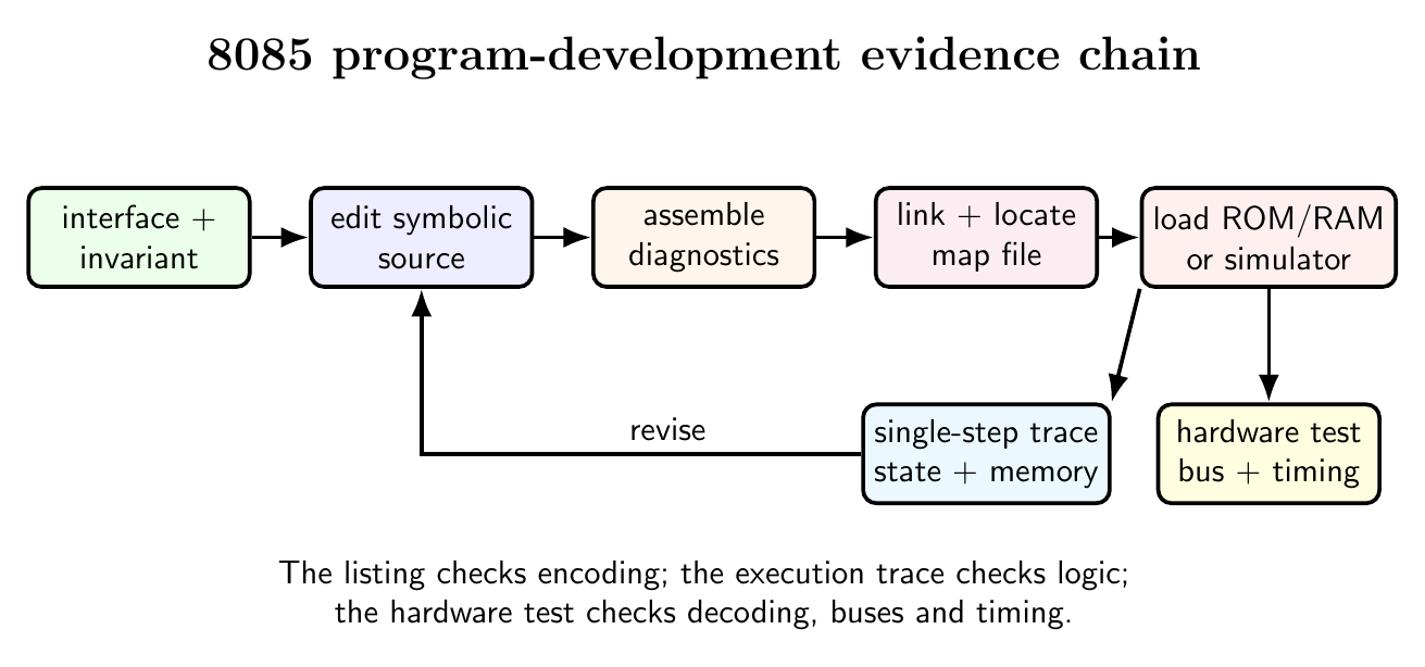
A defensible programming process begins with an interface specification: input locations and ranges, output representation, registers modified, flag contract, stack requirement and termination condition. The algorithm is then expressed as flow or structured pseudocode with loop invariants. Register allocation follows from the live values required simultaneously.
After editing, assembly should be treated as a mathematical encoding check. Inspect the listing to confirm origins, instruction lengths, low-byte-first address operands and branch targets. Inspect the symbol map for accidental overlap of code, data, stack and I/O-related buffers. Link and locate modules only after their public and external interfaces agree.
Testing proceeds first with small cases whose complete state evolution is known. A simulator or monitor can single-step the program while observing $PC$, $SP$, registers, flags and modified memory. Breakpoints should be placed at loop entry, loop exit and exceptional paths. The trace is compared with an invariant, not merely with the final answer. Boundary cases include zero count, one element, maximum unsigned value, signed overflow, carry across bytes and aliased source/destination regions.
Hardware validation then checks assumptions absent from an instruction-set simulator: reset vector contents, clock frequency, memory decoding, bus timing, port addresses, interrupt polarity and electrical handshakes. A correct object file loaded at the wrong origin is still an incorrect executable system.
For code review, every subroutine and ISR should have a compact contract such as
Input: HL -> first byte, B = count (1...255)
Output: A = checksum
Preserves: DE
Destroys: flags, B, HL
Stack: 2 bytes for return address only
This makes separately assembled modules composable and permits stack and timing bounds to be derived before integration.
Preparation questions
- Translate the example source program into bytes and justify every assigned address.
- Explain why a forward reference requires a symbol-table phase, using a three-byte branch instruction.
- Write pass-1 and pass-2 records for source containing
ORG,EQU,DB,DSand a forwardJNZ. - Distinguish source code, listing, object module, load image, symbol table and cross-reference listing.
- Derive the low and high bytes emitted for a branch to $A73C_H$.
- Explain how a linker and locator transform two relocatable modules into an absolute 8085 image.
- Design a test trace that distinguishes an incorrect loop bound from an incorrect branch target.
- State a complete interface contract for a subroutine that finds the maximum byte in an array.


Discussion