

21 May 2025
8085 Stack Organization and Stack Operations
Descending-stack organization, stack-pointer micro-operations, byte ordering, PUSH and POP, PSW storage, XTHL, SPHL and quantitative stack allocation.
The stack is a last-in, first-out area of read-write memory used for temporary preservation of register pairs, program status and return addresses. It is not a separate memory inside the 8085. The processor supplies a 16-bit stack-pointer register $SP$, while the programmer must reserve suitable RAM and initialize $SP$ before executing any instruction that uses the stack.
The 8085 implements a descending stack. A push or subroutine call decrements $SP$ before storing each byte, so the stack grows toward lower addresses. A pop or return reads a byte from the address currently held in $SP$ and then increments $SP$, so removal moves the top of stack toward higher addresses. No hardware boundary register detects overflow or underflow.
Stack-pointer convention and memory allocation
Suppose RAM locations $9A00_H$ through $9AAE_H$ are reserved for the stack. An empty stack may be initialized by
LXI SP,9AAFH
The initial value is one address above the first location that a push will occupy. If $B=2A_H$ and $C=4C_H$, PUSH B performs
followed by
\[SP\leftarrow SP-1,\qquad [SP]\leftarrow C.\]Consequently the final value is $SP=9AAD_H$, with $[9AAE_H]=2A_H$ and $[9AAD_H]=4C_H$.
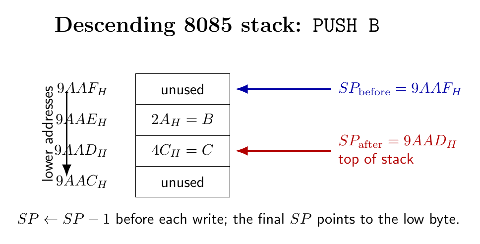
The word is therefore arranged in the usual 8085 little-endian form at the final stack address:
\[[SP]=\text{low byte},\qquad [SP+1]=\text{high byte}.\]For an allocated interval $A_{min}$ through $A_{max}$, initialization with $SP_0=A_{max}+1$ permits at most
\[N_{\max}=\left\lfloor\frac{SP_0-A_{min}}{2}\right\rfloor\]complete 16-bit stack entries. The stack must not collide with variables, buffers or memory-mapped data structures below it.
PUSH and POP micro-operations
The legal register-pair operands of PUSH and POP are B, D, H and PSW. In Intel notation, PUSH B means the pair $BC$, not register $B$ alone; similarly PUSH D means $DE$ and PUSH H means $HL$.
For a pair $(R_H,R_L)$, the operations are
\[\begin{aligned} \texttt{PUSH }R:\quad &SP\leftarrow SP-1, & [SP]&\leftarrow R_H,\\ &SP\leftarrow SP-1, & [SP]&\leftarrow R_L; \end{aligned}\]and
\[\begin{aligned} \texttt{POP }R:\quad R_L&\leftarrow[SP], & SP&\leftarrow SP+1,\\ R_H&\leftarrow[SP], & SP&\leftarrow SP+1. \end{aligned}\]The source pair is unchanged by PUSH. POP B, POP D and POP H do not alter the condition flags. POP PSW is different because restoring the flags is its defined purpose.
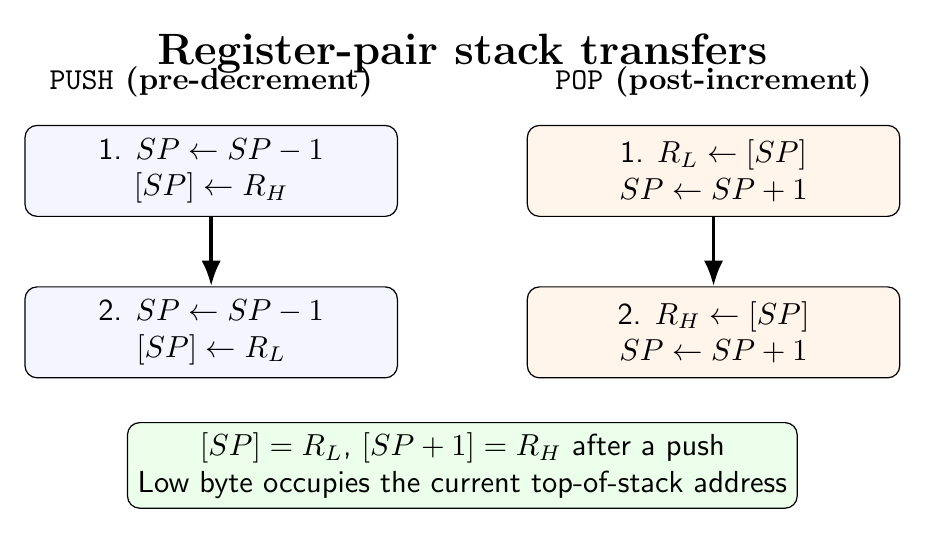
The bus activity reflects these definitions. PUSH requires an opcode fetch and two memory-write transfers, whereas POP requires an opcode fetch and two memory-read transfers. Wait states may lengthen a transfer without changing the architectural sequence.
Program Status Word on the stack
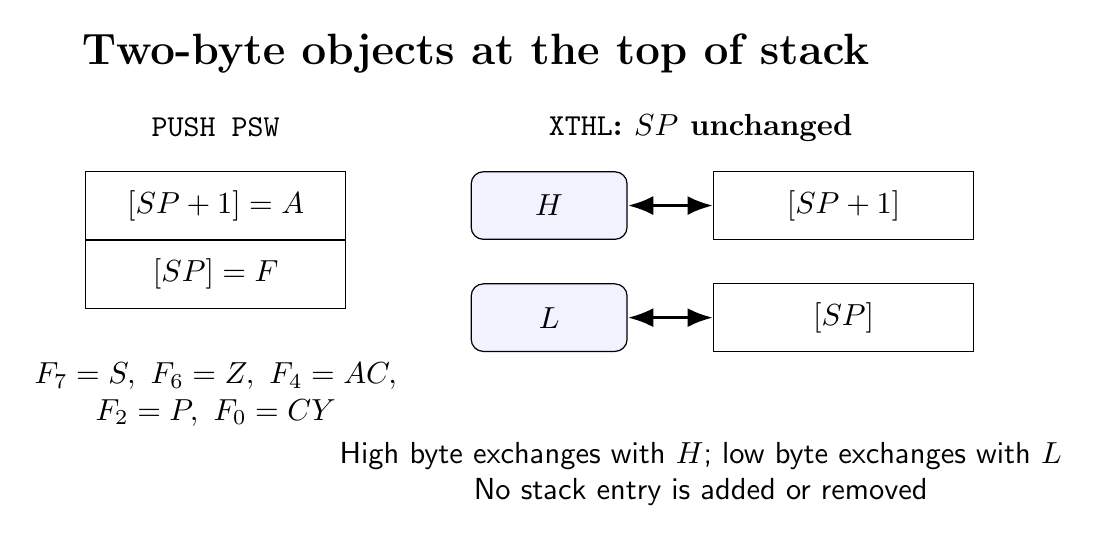
The program status word pairs the accumulator with the condition-flag byte. PUSH PSW first stores $A$ as the high byte and then stores the formatted flags as the low byte. After completion,
The meaningful flag positions are
\[F_7=S,\quad F_6=Z,\quad F_4=AC, \quad F_2=P,\quad F_0=CY.\]The remaining bit positions are not programmer flags and should not be used to preserve application information. POP PSW loads the flag byte from $[SP]$, increments $SP$, loads $A$ from $[SP]$, and increments $SP$ again. Thus it restores both the accumulator and arithmetic condition state.
A routine that may change every work register can preserve the machine state as follows:
        PUSH PSW
        PUSH B
        PUSH D
        PUSH H
        ; body of routine
        POP  H
        POP  D
        POP  B
        POP  PSW
The reverse restoration order is compulsory. If the routine pops a different number of bytes, a later RET can interpret saved data as a return address and transfer control to an unintended location.
Complete numerical stack trace
Let initially
\[SP=4000_H,\qquad BC=1234_H,\qquad DE=ABCD_H.\]Execute
        PUSH B
        PUSH D
        POP  H
        POP  B
The states are:
| Instruction | New $SP$ | Memory or register consequence |
|---|---|---|
PUSH B |
$3FFE_H$ | $[3FFF_H]=12_H$, $[3FFE_H]=34_H$ |
PUSH D |
$3FFC_H$ | $[3FFD_H]=AB_H$, $[3FFC_H]=CD_H$ |
POP H |
$3FFE_H$ | $L=CD_H$, $H=AB_H$, hence $HL=ABCD_H$ |
POP B |
$4000_H$ | $C=34_H$, $B=12_H$, hence $BC=1234_H$ |
This trace demonstrates both LIFO ordering and low-byte placement at the current stack pointer. The two pushes allocate four bytes; the two pops release exactly four bytes.
XTHL and SPHL
XTHL exchanges $L$ with $[SP]$ and $H$ with $[SP+1]$:
The value of $SP$ is unchanged. For example, if $SP=2FF0_H$, $HL=0DF0_H$, $[2FF0_H]=3C_H$ and $[2FF1_H]=0B_H$, then after XTHL,
This instruction can exchange a parameter or saved word at the top of stack without first changing the depth.
SPHL performs
It neither reads nor writes stack memory and does not change $HL$. It is useful when a program computes a new stack base in $HL$, but an arbitrary SPHL discards access to the previous stack unless that pointer has been saved elsewhere. LXI SP,d16 is the usual initialization instruction; INX SP and DCX SP can adjust $SP$ but must not break the two-byte organization expected by saved words and return addresses.
Stack depth in nested execution
At any instant define $n_P$ as the number of unmatched pair pushes, $n_C$ the number of active calls or restart-like transfers that saved a return address, and $n_I$ the number of interrupt entries whose saved program counters have not yet been removed. The occupied stack depth in bytes is
\[D=2(n_P+n_C+n_I).\]The required allocation is governed by the maximum over every possible execution path,
\[\boxed{D_{\max}=2\max_t[n_P(t)+n_C(t)+n_I(t)]}.\]If the main program can be interrupted while it has two pushed pairs and is three calls deep, and the interrupt routine pushes four more pairs, the worst depth is
\[D_{\max}=2(2+3+1+4)=20\ \text{bytes}.\]Additional space should be reserved for further nesting and for any interrupt that can pre-empt the current service routine. Because the 8085 provides no automatic stack-limit exception, this calculation is a program-design obligation.
Preparation questions
- Explain why the 8085 stack is called a descending last-in, first-out stack.
- Starting with $SP=5000_H$ and $DE=7A35_H$, show the address and data after
PUSH D. - Derive the micro-operations of
POP Hand state which byte enters each register. - Describe the exact memory layout produced by
PUSH PSWand the effect ofPOP PSW. - For a specified sequence of pushes, calls, pops and returns, determine the maximum stack depth and lowest value of $SP$.
- Distinguish
XTHL,SPHLandLXI SP,d16in terms of data transfers and stack depth. - Explain how an unbalanced push/pop sequence can corrupt a subroutine return address.


Discussion