

23 May 2025
8085 Subroutines: CALL, RET, RST and Program Linkage
Return-address formation, CALL and RET stack transfers, conditional linkage, nested routines, restart vectors, register preservation and parameter-passing conventions.
A subroutine is a separately located instruction sequence that performs a defined operation and then returns control to its caller. It eliminates repeated copies of the same code, provides a natural interface between program modules and permits hierarchical program design. In the 8085, linkage is implemented through the program counter and the descending RAM stack.
A correct subroutine convention must specify four matters: how control enters and leaves the routine, where arguments are supplied, where results are returned, and which registers the routine is permitted to destroy. The processor implements only the control-transfer mechanism; the register and parameter convention is a programmer agreement.
Unconditional CALL operation
CALL target is a three-byte instruction. Its machine-code form is
The 8085 stores a 16-bit immediate address low byte first. If CALL 3400H begins at $2050_H$, the instruction occupies addresses $2050_H$, $2051_H$ and $2052_H$. After these bytes have been read, the program counter contains the next sequential address,
The processor pushes this return address and then loads the target:
\[\begin{aligned} SP&\leftarrow SP-1, & [SP]&\leftarrow PCH_{\rm return},\\ SP&\leftarrow SP-1, & [SP]&\leftarrow PCL_{\rm return},\\ PC&\leftarrow target. \end{aligned}\]Thus, if $SP=4000_H$ before the call, after it $SP=3FFE_H$, $[3FFF_H]=20_H$, $[3FFE_H]=53_H$ and $PC=3400_H$.
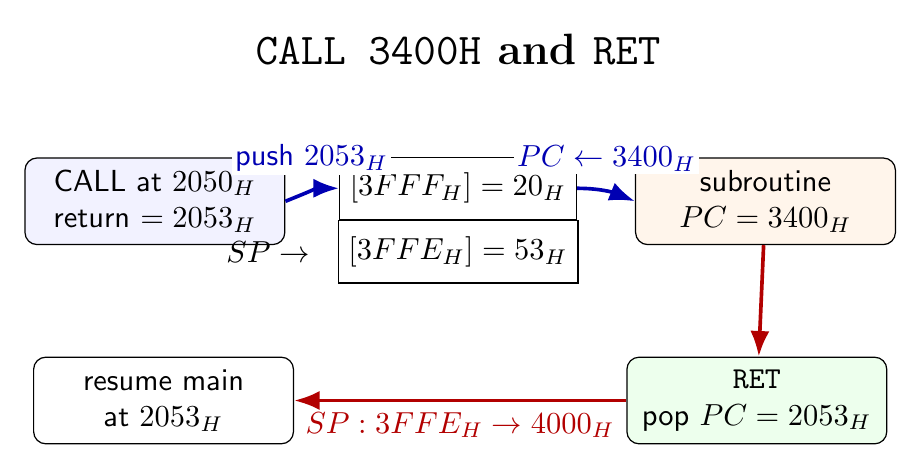
The bus work consists of three instruction-byte reads and two stack writes. The condition flags are not altered by CALL.
RET operation and the linkage invariant
An unconditional RET is a one-byte instruction with opcode $C9_H$. It performs
No return address is encoded in RET; the address comes entirely from the current top of stack. A fundamental linkage invariant is therefore
If a subroutine pushes register pairs, it must pop the same pairs in reverse order before returning. Otherwise RET consumes saved register data as an address. Similarly, changing $SP$ with SPHL, INX SP or DCX SP inside a routine requires an exact restoration before RET.
The customary callee-save pattern is
ROUTINE: PUSH PSW
         PUSH B
         PUSH D
         PUSH H
         ; routine body
         POP  H
         POP  D
         POP  B
         POP  PSW
         RET
Saving every register is safe but not always efficient. A documented interface may instead declare selected registers as volatile. For example, a routine returning an eight-bit result in $A$ cannot restore the old accumulator with POP PSW; it should preserve only the registers not used for its result.
Nested subroutines and stack depth
A subroutine may call another subroutine. Each active call contributes a distinct two-byte return address. If the main program calls SUB1, and SUB1 calls SUB2, the address returning from SUB2 to SUB1 becomes the newer top-of-stack entry at lower memory addresses than the older address returning from SUB1 to the main program. LIFO removal therefore produces the correct control sequence.
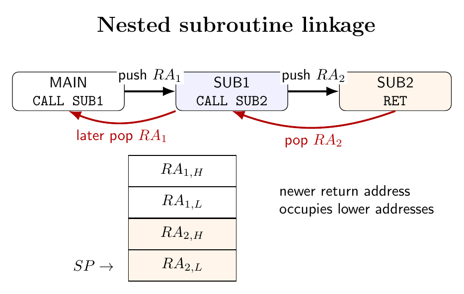
If the maximum call nesting is $d$, and active routines collectively have at most $p$ unmatched pair pushes, then the required stack allocation for ordinary linkage is at least
\[D_{\max}=2(d+p)\ \text{bytes},\]before allowing for interrupt entry. Recursion is possible because each call has its own return address, but the 8085 has no frame pointer, automatic local-variable allocation or stack-limit protection. A recursive routine must define its own parameter and local-data representation and must prove that recursion terminates before RAM is exhausted.
Conditional CALL and conditional RET
The eight flag conditions are zero/nonzero, carry/no carry, minus/positive and parity even/odd. They produce conditional calls
CZ CNZ CC CNC CM CP CPE CPO
and corresponding conditional returns
RZ RNZ RC RNC RM RP RPE RPO
A conditional call is still a three-byte instruction. If its condition is true, it pushes the return address and transfers to the target exactly like CALL. If false, execution continues after the instruction and the stack remains unchanged. A conditional return pops $PC$ only when its condition is true; otherwise it proceeds to the following byte in the current routine.
This permits compact multi-exit routines. For example,
CHECK:  CMP  M
        RZ           ; return immediately if A = [HL]
        ; process unequal case
        RET
The flags tested must have been established intentionally. Data-transfer instructions such as MOV do not update the arithmetic flags, so a conditional return after MOV would test an older condition.
RST as a one-byte call
RST n, where $0\le n\le7$, is a one-byte special call. Its opcode and destination are
The opcode format is $11nnn111_2$. The eight software destinations are
| Instruction | Opcode | Vector address |
|---|---|---|
RST 0 |
$C7_H$ | $0000_H$ |
RST 1 |
$CF_H$ | $0008_H$ |
RST 2 |
$D7_H$ | $0010_H$ |
RST 3 |
$DF_H$ | $0018_H$ |
RST 4 |
$E7_H$ | $0020_H$ |
RST 5 |
$EF_H$ | $0028_H$ |
RST 6 |
$F7_H$ | $0030_H$ |
RST 7 |
$FF_H$ | $0038_H$ |
Like CALL, RST pushes the next-instruction $PC$—the address following its one-byte opcode—before loading the vector, so a RET can resume the interrupted sequence. Only eight bytes separate adjacent software vectors. A vector commonly contains JMP service to reach a longer routine elsewhere.
The hardware inputs TRAP and RST 5.5, 6.5 and 7.5 generate related internal restart actions but use the intermediate vectors $0024_H$, $002C_H$, $0034_H$ and $003C_H$. Their priority, trigger modes and masking are treated with the complete interrupt system.
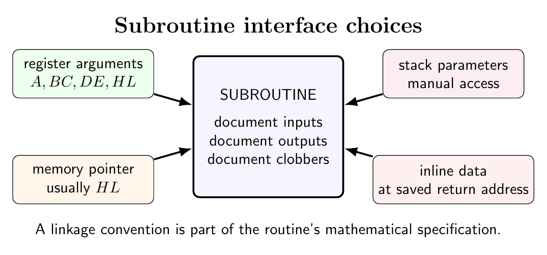
Parameter passing and return values
The simplest interfaces pass arguments in registers:
        LXI  H,2400H       ; array address
        MVI  B,10          ; number of bytes, B > 0
        CALL SUM8
        ; A contains sum modulo 256; CY is not a total-overflow count

SUM8:  XRA  A
NEXT:  ADD  M
        INX  H
        DCR  B
        JNZ  NEXT
        RET
The interface declares $HL$ and $B$ as inputs, $A$ as output, and $HL$, $B$ and arithmetic flags as destroyed. If the caller needs their old values, it must save them or the routine must adopt a callee-save convention.
Arguments can also occupy fixed RAM locations, be addressed through a pointer in $HL$, or be placed after the CALL instruction. The last technique makes the saved return address point to inline data; the routine must read that address, advance it over the parameters and replace or emulate the corrected return. It is compact but more fragile than register or pointer passing.
The stack can carry parameters, but the 8085 has no instruction of the form $[SP+k]$. Access normally requires controlled POP/PUSH sequences, XTHL, or copying $SP$ to $HL$ through a designed sequence. Interrupts must not observe a temporarily malformed stack layout.
Code-size criterion
Suppose an operation requires $L$ bytes when written inline and is used $k$ times. Repetition costs $kL$ bytes. A single subroutine with $k$ three-byte calls and a one-byte RET costs approximately
The code-space saving is
\[\boxed{\Delta=(k-1)L-3k-1}.\]For $L=40$ and $k=4$, inline code requires $160$ bytes, whereas the subroutine organization requires $40+12+1=53$ bytes, saving $107$ bytes. The tradeoff is execution time for linkage, two stack bytes per active call, and a requirement for writable memory.
Preparation questions
- Derive the stack and program-counter micro-operations performed by an unconditional
CALL. - Encode
CALL 4A30Hinto three machine-code bytes and determine the return address if it begins at $2100_H$. - Explain the stack-pointer invariant that must hold immediately before
RET. - Trace two nested calls and returns, including the byte order of both saved addresses.
- Compare conditional calls and conditional returns for true and false flag conditions.
- Derive the opcode and vector address of every
RST ninstruction. - Design a register-preservation and parameter-passing convention for an array-processing subroutine.
- Obtain the break-even condition for replacing $k$ inline copies of an $L$-byte operation by a subroutine.


Discussion