

01 May 2025
Microprocessors, Microcontrollers, and Microcomputers
A system-level comparison of processing units, integrated controllers, complete microcomputers, buses, memory organization, and address-space calculations.
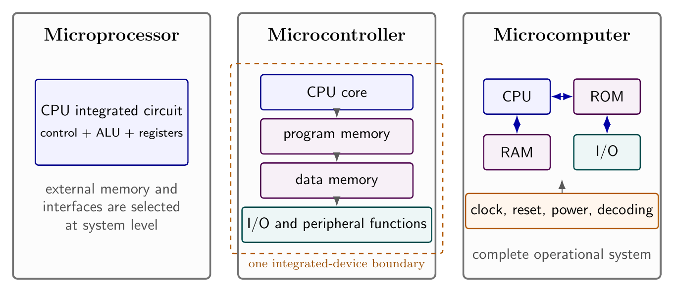
The terms microprocessor, microcontroller, and microcomputer describe related but different levels of a digital system. A microprocessor is primarily a programmable central processing unit implemented as an integrated circuit. A microcomputer is a working computer assembled around such a processor, with memory, input/output interfaces, timing, power and interconnections. A microcontroller places a processor core and a useful set of memory and peripheral resources within one integrated device. The distinction is therefore architectural: it concerns what boundary is being described, not merely the clock rate, word length or physical size.
The Intel 8085 is an instructive microprocessor example. To execute a stored program it must participate in a larger system containing program memory, writable memory when variables or a stack are required, and interfaces to external devices. The programmer sees an 8-bit data path, a 16-bit address space, registers, condition flags, a stack and input/output ports. Those visible resources connect software operations to the external microcomputer.
Three system boundaries
A microprocessor fetches instruction bytes, decodes them, performs arithmetic or logical operations, and controls transfers among registers, memory and input/output. The word micro historically identifies the integrated implementation of the CPU; it does not mean that memory and peripherals are automatically included. The processor is consequently a component from which different systems can be constructed.
A microcomputer includes everything needed to carry out the intended computation. Its program may reside in ROM, while RAM holds changing data and the stack. Address-decoding logic selects one physical memory or interface for each assigned address. Input and output ports connect the machine to displays, switches, converters or other equipment. A development system and a dedicated embedded instrument can both be microcomputers even though their user interfaces differ greatly.
A microcontroller integrates the CPU with some combination of program memory, data memory, digital input/output and timing or communication peripherals. The high integration reduces external component count and makes control-oriented systems compact. It does not change the stored-program principle: instructions are still fetched, data are still represented as bit patterns, and peripheral registers must still be addressed and controlled. External devices or memory may also be added when the integrated resources are insufficient.
| Term | Boundary being described | Resources necessarily emphasized | Typical design consequence |
|---|---|---|---|
| Microprocessor | CPU integrated circuit | instruction control, ALU, registers and external buses | system designer selects external memory and interfaces |
| Microcontroller | highly integrated control device | CPU plus on-chip memory and peripheral functions | fewer external parts for a defined control task |
| Microcomputer | complete working computer | processor, memory, input/output and support hardware | can execute its intended program and communicate with its environment |
These categories overlap. A microcomputer can use either a stand-alone microprocessor or a microcontroller as its processing element. Likewise, a board containing an 8085 and external devices is not transformed into a microcontroller; it is a microcomputer built around a microprocessor.
Functional organization of a microcomputer
The processor, memory and input/output interfaces exchange information over three conceptual groups of signals. The address bus identifies the selected memory location or port. The data bus carries an instruction byte, operand or result. The control bus qualifies the transfer: it distinguishes reading from writing, coordinates timing, and permits devices to request service or delay a transaction where the hardware provides those facilities.
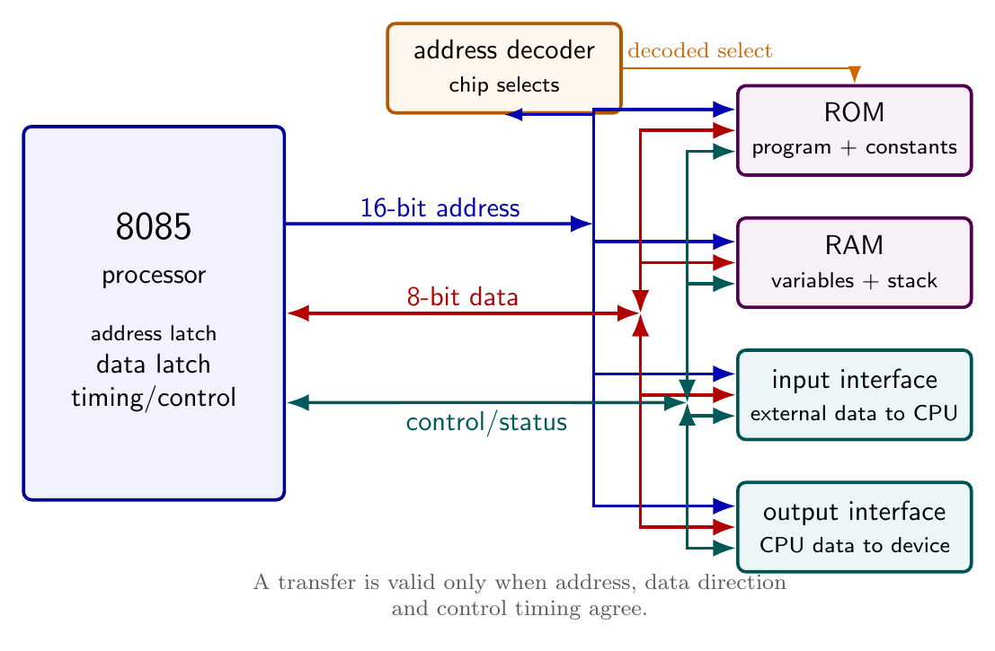
Bus widths answer different questions. If the data path is eight bits wide, one ordinary transfer carries one byte and the ALU directly processes 8-bit quantities. If the address path is sixteen bits wide, there are
\[N_{\text{locations}}=2^{16}=65\,536\]distinct binary address patterns. With byte-addressable memory, the memory address range is $0000_{\mathrm H}$ through $FFFF_{\mathrm H}$ and its capacity is $65\,536$ bytes, conventionally $64\ \mathrm{KiB}$. Data width alone does not determine memory capacity; address width and the size of each addressed unit must also be stated.
The address bus is used predominantly from processor toward memory and interfaces during a processor-initiated transfer. The data bus must be bidirectional: memory drives it during a read, while the processor drives it during a write. Control lines can have different directions because some announce processor actions and others report external conditions.
Stored programs, ROM, RAM and the stack
Program instructions and constant data can be held in ROM, whose contents the processor reads but does not alter during normal execution. RAM supports both reading and writing and therefore holds variables, buffers and self-changing state. Even when the entire program is in ROM, RAM is required if the program writes variables or uses a stack.
The program counter contains the address of the next instruction byte to be fetched. After a byte fetch it advances to the next address. Multi-byte instructions therefore occupy consecutive memory locations. A jump or call replaces the sequential address with a new one. The fetched opcode enters the instruction-decoding path, which produces the internal transfers and external bus cycles required to execute that instruction.
The stack is an area of RAM addressed by the stack pointer. In the 8080/8085 programming model it grows toward lower addresses as items are pushed and retreats toward higher addresses as they are popped. A call saves the return address on the stack before loading the program counter with the subroutine address; a return restores the saved address. The program must initialize the stack pointer to a valid RAM region before stack-dependent operations are used.
Memory space and input/output space
Memory locations and isolated input/output ports are distinct programmer-visible spaces in the 8080/8085 model. A memory operand can be an instruction, constant, variable or stack byte. The 8-bit operand of an IN or OUT instruction selects one of $2^8=256$ port numbers, and data pass through the accumulator. The Intel programming model places the selected port number on both halves of the 16-bit address bus during such a transfer; external decoding and control logic decide which peripheral responds.
Memory-mapped interfaces can instead occupy memory addresses and use memory-transfer instructions, but every allocated interface location then consumes part of the finite memory address map. Isolated input/output preserves the memory map and uses the specialized port instructions. The choice affects decoding hardware, instruction selection and the set of registers through which data can move.
Binary and hexadecimal address calculations
Hexadecimal is a compact notation for buses and memory maps because one hexadecimal digit corresponds to four binary bits. Thus
\[(3A)_{16}=(0011\,1010)_2=(58)_{10}.\]A 16-bit address contains four hexadecimal digits; an 8-bit byte contains two. The numerical value of an address $d_3d_2d_1d_0$ in hexadecimal is
\[A=16^3d_3+16^2d_2+16d_1+d_0,\]where the digits $A$ through $F$ represent decimal $10$ through $15$.
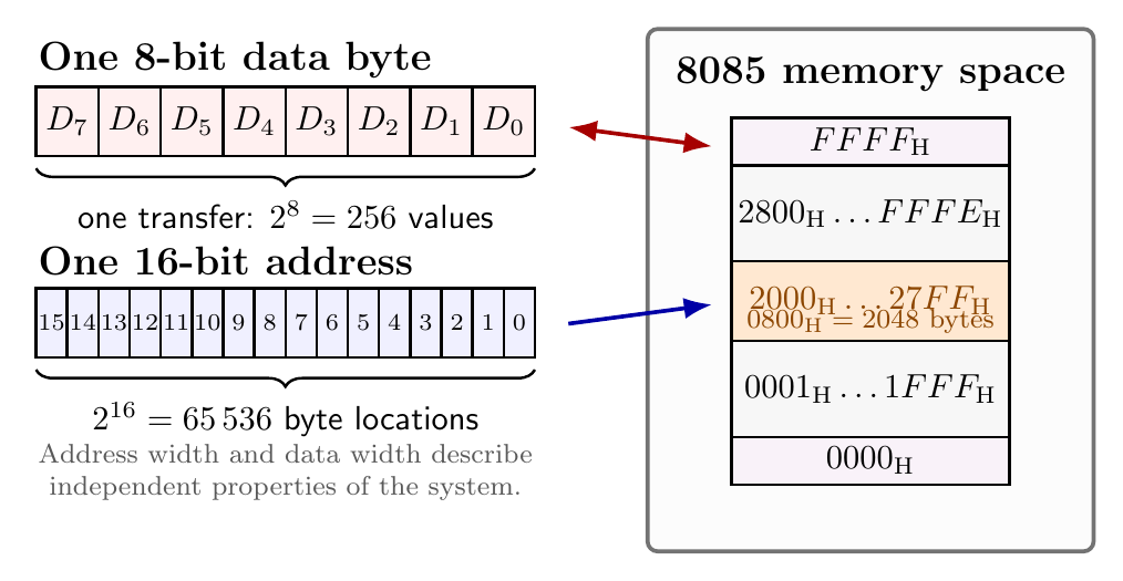
For any inclusive address interval from $A_{\min}$ to $A_{\max}$, its size is
\[N=A_{\max}-A_{\min}+1.\]For example, a RAM assigned $2000_{\mathrm H}$ through $27FF_{\mathrm H}$ occupies
\[27FF_{\mathrm H}-2000_{\mathrm H}+1=0800_{\mathrm H}=2048\]byte locations. The plus one is essential because both endpoints are included. The next non-overlapping address is $2800_{\mathrm H}$.
Selecting an architectural approach
The design decision should follow measurable system requirements. A stand-alone microprocessor is useful when the memory size, interface mix or bus accessibility must be selected independently. A microcontroller is attractive when integrated peripherals match the control problem and reductions in board area, wiring and component count are valuable. Calling one category universally faster or more capable is unsound: performance depends on the particular devices, memory organization, instruction workload and external timing.
The same disciplined separation helps in troubleshooting. A wrong arithmetic result may originate in software or the processor data path; a wrong address may select the wrong memory device; a correct internal result may fail to reach the outside world because the interface or control timing is incorrect. Thinking in terms of CPU, memory, input/output and buses localizes the fault before individual signals are examined.
Primary sources
- Intel, MCS-80 User’s Manual, October 1977
- Intel, 8080/8085 Assembly Language Programming Manual, November 1978
Preparation questions
- Distinguish a microprocessor, a microcontroller and a microcomputer by the system boundary each term describes.
- Draw a processor–memory–input/output system and explain the roles and directions of its address, data and control buses.
- Why does an 8-bit processor with a 16-bit address bus have $65\,536$ byte addresses rather than 256?
- Calculate the inclusive size of the address block $A400_{\mathrm H}$–$AFFF_{\mathrm H}$ and state the first address after it.
- Explain why an ROM-resident program can still require RAM.
- Compare isolated and memory-mapped input/output from the viewpoints of address allocation and instruction use.
- Trace the conceptual fetch–decode–execute sequence and explain how a jump changes the otherwise sequential flow.


Discussion