

25 Jun 2025
Op-Amp Comparators and Schmitt Trigger
Open-loop comparison, zero crossing, regenerative thresholds, hysteresis and switching limitations of operational amplifiers.
A comparator converts an analog voltage difference into one of two output levels. An operational amplifier can perform this function in open-loop operation, although a purpose-built comparator is generally faster and recovers more cleanly from saturation. Positive feedback converts the simple comparator into a Schmitt trigger having two distinct switching thresholds. The resulting hysteresis rejects small input fluctuations and is central to bistable and relaxation-oscillator circuits.
Let $v_d=v_+-v_-$. In its linear range an op amp obeys $v_o=A_0v_d$, but its very large open-loop gain drives the output to a limiting level for even a small differential input. Denote the actual output limits by $V_{OH}$ and $V_{OL}$; they need not equal the supply rails or be symmetric.
Open-loop comparator
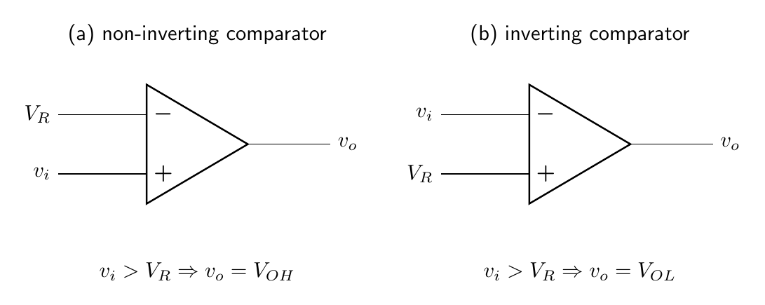
For a non-inverting comparator with $v_i$ at $v_+$ and reference $V_R$ at $v_-$,
\[\boxed{ v_o=\begin{cases} V_{OH},&v_i>V_R,\\ V_{OL},&v_i<V_R. \end{cases}}\]An inverting comparator interchanges the two output states. In the ideal model the transition occurs at $v_i=V_R$. With input offset voltage $V_{OS}$ the effective threshold is displaced approximately by $V_{OS}$, with sign determined by the input convention. Input bias currents create further shifts through source resistances.
For finite open-loop gain, the non-inverting comparator obeys $v_o=A_0(v_i-V_R)$ while it remains unsaturated. The input interval required for the output to traverse its full range is
\[\Delta v_i=\frac{V_{OH}-V_{OL}}{A_0}.\]At dc this interval may be only microvolts, but $A_0$ falls with frequency. Dynamic switching is consequently governed by open-loop bandwidth, slew rate and propagation delay rather than by dc gain alone.
If $v_i(t)$ changes with slope $S=dv_i/dt$, an input-referred noise or threshold uncertainty $v_n$ produces timing uncertainty of order
\[\boxed{\Delta t\simeq\frac{v_n}{\lvert S\rvert}}.\]Thus a slowly varying input is especially susceptible to repeated transitions and timing jitter near the threshold.
Zero-crossing detector
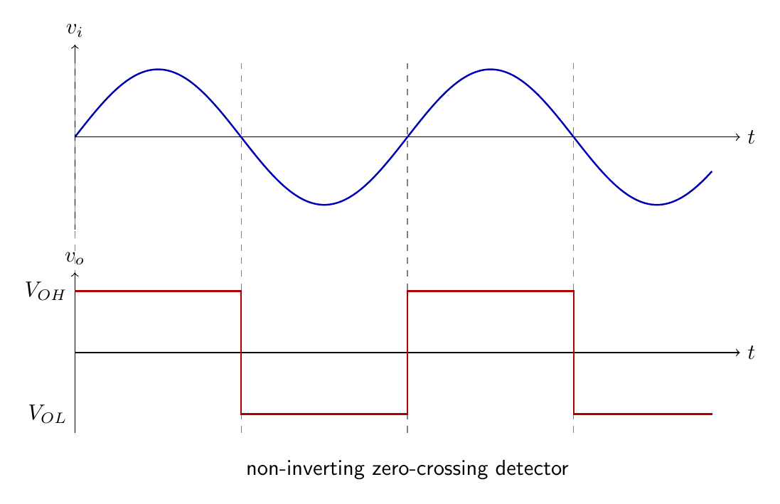
Taking $V_R=0$ produces a zero-crossing detector. In the non-inverting form,
\[v_o=V_{OH}\quad(v_i>0),\qquad v_o=V_{OL}\quad(v_i<0).\]A sinusoidal input $v_i=V_m\sin\omega t$ ideally produces transitions at $t=n\pi/\omega$. It is therefore converted to a two-level waveform with the same repetition frequency. Offset voltage changes the crossing condition to $V_m\sin\omega t\simeq V_{OS}$ and shifts the transition phase. For $\lvert V_{OS}\rvert\ll V_m$, the timing error close to a zero crossing is approximately
\[\Delta t\simeq\frac{V_{OS}}{\omega V_m}.\]Noise around zero can cause multiple output transitions. Hysteresis prevents this behavior by requiring a finite input excursion before the state can reverse.
Inverting Schmitt trigger
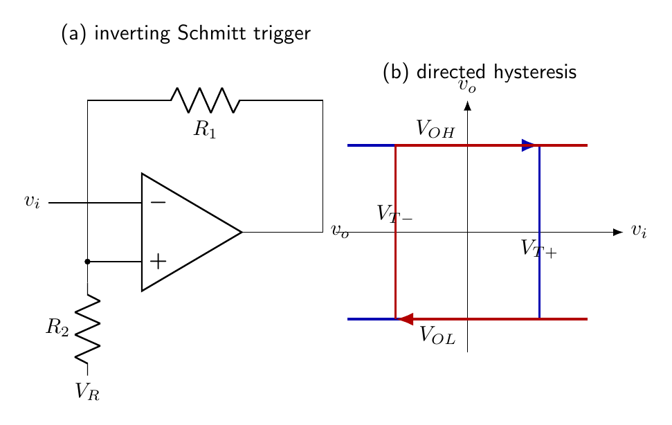
Consider an inverting comparator with $v_i$ applied to $v_-$. The non-inverting node is connected to $v_o$ through $R_1$ and to a dc reference $V_R$ through $R_2$. Neglecting input current,
\[v_+=\frac{R_2}{R_1+R_2}v_o+ \frac{R_1}{R_1+R_2}V_R.\]Define
\[\beta=\frac{R_2}{R_1+R_2},\qquad 0<\beta<1.\]Then
\[v_+=\beta v_o+(1-\beta)V_R.\]Suppose the output is initially high. As $v_i$ rises, it switches the output low when $v_i=v_+$, giving the upper threshold
\[\boxed{V_{T+}=\beta V_{OH}+(1-\beta)V_R.}\]With the output low, the threshold at the non-inverting input changes. As $v_i$ falls, the output switches high at
\[\boxed{V_{T-}=\beta V_{OL}+(1-\beta)V_R.}\]The hysteresis width is
\[\boxed{V_H=V_{T+}-V_{T-}=\beta(V_{OH}-V_{OL}).}\]For symmetric limiting $V_{OH}=+V_S$, $V_{OL}=-V_S$, and $V_R=0$,
\[\boxed{V_{T+}=+\beta V_S,\qquad V_{T-}=-\beta V_S,\qquad V_H=2\beta V_S.}\]This is an inverting hysteresis characteristic: increasing $v_i$ through $V_{T+}$ makes the output jump from high to low, whereas decreasing it through $V_{T-}$ makes the output jump from low to high.
If input offset $V_{OS}$ is represented as a small source at the non-inverting input, both thresholds acquire approximately the same displacement. Their separation is unchanged to first order, but the centre of the hysteresis loop moves. If a bias current $I_{B+}$ flows into the feedback-divider node, the stated direction gives
\[v_+=\beta v_o+(1-\beta)V_R-I_{B+}(R_1\parallel R_2).\]The thresholds shift by the final term. Source resistance at the inverting input produces a further $I_{B-}R_s$ error. Signed current conventions are essential because data sheets usually quote magnitudes.
Threshold design
For symmetric desired thresholds $\pm V_T$ and symmetric outputs $\pm V_S$,
\[\beta=\frac{V_T}{V_S}.\]Since $\beta=R_2/(R_1+R_2)$,
\[\boxed{\frac{R_1}{R_2}=\frac{1-\beta}{\beta}.}\]For example, if $V_S=12\,\mathrm{V}$ and the desired thresholds are $\pm3\,\mathrm{V}$, then $\beta=0.25$ and $R_1/R_2=3$. Values $R_1=30\,\mathrm{k\Omega}$ and $R_2=10\,\mathrm{k\Omega}$ realize the ratio, provided loading and input currents are negligible.
For nonsymmetric output levels and specified thresholds, the relations
\[V_{T+}-V_{T-}=\beta(V_{OH}-V_{OL})\]and
\[V_R=\frac{V_{T+}-\beta V_{OH}}{1-\beta}\]determine $\beta$ and $V_R$. Using the measured $V_{OH}$ and $V_{OL}$ is more accurate than substituting nominal supply rails.
The threshold centre is
\[V_C=\frac{V_{T+}+V_{T-}}2 =\beta\frac{V_{OH}+V_{OL}}2+(1-\beta)V_R.\]A zero reference therefore does not centre the loop on zero if the output limits are asymmetric. Choosing
\[V_R=-\frac{\beta(V_{OH}+V_{OL})}{2(1-\beta)}\]centres the ideal thresholds, although output-level drift still changes the hysteresis width.
Non-inverting Schmitt form
Hysteresis can also be produced by feeding both input and output into the non-inverting node while holding $v_-=V_R$. Let $R_i$ connect $v_i$ to $v_+$ and $R_f$ connect $v_o$ to $v_+$. At switching, $v_+=V_R$, so KCL gives
\[\frac{v_i-V_R}{R_i}+\frac{v_o-V_R}{R_f}=0.\]The input threshold belonging to a particular output state is
\[v_i=V_R-\frac{R_i}{R_f}(v_o-V_R).\]With output low, a rising input switches high at
\[V_{T+}=V_R-\frac{R_i}{R_f}(V_{OL}-V_R),\]whereas with output high a falling input switches low at
\[V_{T-}=V_R-\frac{R_i}{R_f}(V_{OH}-V_R).\]Its hysteresis width is $(R_i/R_f)(V_{OH}-V_{OL})$. Unlike the earlier inverting form, its output follows the input direction outside the band. The resistor definitions of these two topologies must not be interchanged.
Noise immunity
Assume the output has switched low after $v_i$ exceeded $V_{T+}$. It cannot switch high until $v_i$ falls below $V_{T-}$. Any noise fluctuation smaller than the distance to the opposite threshold leaves the state unchanged. The hysteresis should exceed the expected peak-to-peak input noise with adequate margin, but excessive hysteresis increases the input excursion and timing displacement required for switching.
For a slowly varying ramp with slope $S$, the time between its crossings of the two thresholds is
\[\Delta t_H=\frac{V_H}{\lvert S\rvert}.\]This interval quantifies the immunity to rapid retriggering but also the hysteretic difference in switching time.
Practical op-amp limitations
An ordinary op amp used open loop is affected by saturation recovery, slew rate and limited output swing. Its input common-mode range may be violated even though the differential voltage is small. Some op amps exhibit phase reversal outside the common-mode range. Large differential input voltages may exceed internal protection limits. The output transition time is at least of order
\[t_{\mathrm{slew}}\geq\frac{\lvert V_{OH}-V_{OL}\rvert}{\mathrm{SR}}.\]Propagation delay generally depends on input overdrive. A comparator designed for switching often provides faster recovery and logic-compatible output stages; some require a pull-up resistor because they use an open-collector or open-drain output.
Large overdrive may push internal op-amp stages deeply into saturation and lengthen recovery. A clamp that prevents deep saturation can improve speed, but adds capacitance and loading. Propagation delay is therefore specified at particular input-overdrive values: larger overdrive normally gives a faster decision, while a signal that barely crosses threshold gives the greatest timing uncertainty.
Positive feedback must be laid out carefully. Output-current spikes coupled capacitively to the input can cause false transitions. Supply decoupling, a controlled source impedance and a clean reference are part of the threshold design. For high-speed signals, parasitic capacitance in the feedback divider introduces a transient threshold different from the dc value.
Window comparison
Two comparators can detect whether an input lies inside a specified interval. With $V_L<V_U$, one comparator tests $v_i>V_L$ and the other tests $v_i<V_U$; logic combination produces the window output. Although not a regenerative oscillator, this arrangement illustrates that precise threshold systems depend on reference accuracy, offset, noise and output logic compatibility.
Input protection must preserve the intended threshold. A series resistor limits differential-input current, but its voltage drop due to bias current contributes error. Clamp diodes protect against large excursions but add leakage and capacitance. Their return node should be chosen so that fault current does not disturb the precision reference. These effects become especially important when thresholds are only a few millivolts.
Threshold verification should record both sweep directions and the actual saturated output levels, because a one-direction measurement cannot reveal hysteresis.
Preparation questions
- Distinguish non-inverting and inverting comparator transfer characteristics using $v_d=v_+-v_-$.
- Derive the timing error of a sinusoidal zero-crossing detector due to a small input offset voltage.
- Derive both thresholds and the hysteresis width of the biased inverting Schmitt trigger.
- Design a Schmitt trigger with $V_{OH}=11.5\,\mathrm{V}$, $V_{OL}=-10.8\,\mathrm{V}$ and thresholds $+2.5\,\mathrm{V}$ and $-2.0\,\mathrm{V}$.
- Explain how hysteresis suppresses multiple transitions caused by input noise.
- Discuss why a general-purpose op amp may be inferior to a comparator in fast switching service.


Discussion