

27 Jun 2025
Op-Amp Bistable, Astable and Monostable Multivibrators
Regenerative switching, stable states, relaxation periods, one-shot pulse width and nonideal timing.
A multivibrator is a regenerative circuit having two output levels. Positive feedback produces rapid transitions, while an RC network or an external trigger determines when a transition occurs. A bistable multivibrator has two stable states, a monostable has one stable state and one temporary state, and an astable has no stable state and switches periodically without an external trigger.
The derivations use an op amp whose output levels are $+V_S$ and $-V_S$, assumed symmetric unless stated otherwise. A divider applies $v_+=\beta v_o$ to the non-inverting input, where
\[\beta=\frac{R_2}{R_1+R_2},\qquad 0<\beta<1.\]The switching thresholds at the other input are therefore $+\beta V_S$ and $-\beta V_S$. Actual circuits should use measured $V_{OH},V_{OL}$ when output swing is asymmetric.
Bistable multivibrator
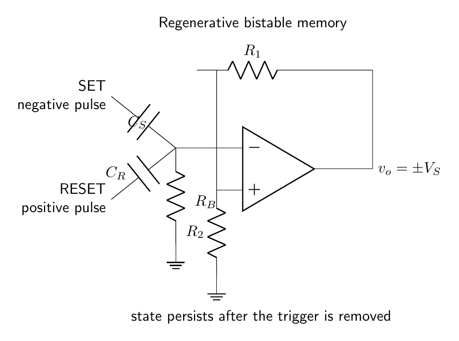
The bistable is an inverting Schmitt trigger operated as a memory element. With $v_o=+V_S$, positive feedback establishes the upper threshold $+\beta V_S$. A positive RESET pulse coupled to the inverting input drives $v_-$ above that threshold and switches the output low. After switching to $-V_S$, the threshold becomes $-\beta V_S$; a negative SET pulse drives $v_-$ below it and switches the output high. The return resistor $R_B$ fixes the dc reference of the comparison input after either capacitively coupled pulse has ended.
Both states are stable because, after the triggering disturbance is removed, the sign of $v_+-v_-$ reinforces the existing output. The state can represent one bit. Separate set and reset networks, or a single input driven beyond opposite thresholds, control it.
Astable multivibrator circuit
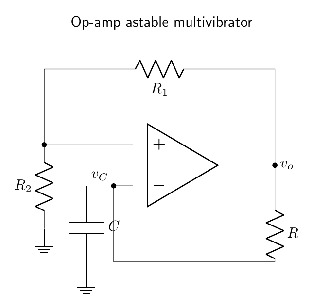
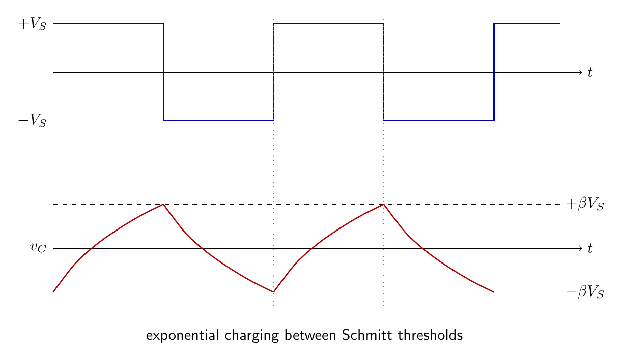
In the astable circuit the non-inverting input receives $\beta v_o$. The inverting input is the capacitor voltage $v_C$; the capacitor is connected to ground and charged from the output through $R$. Suppose the output has just switched to $+V_S$. The capacitor voltage is continuous and initially equals the previous threshold,
\[v_C(0)=-\beta V_S.\]It now approaches $+V_S$ with time constant $RC$:
\[v_C(t)=V_S+[v_C(0)-V_S]e^{-t/RC}.\]Substituting the initial value,
\[v_C(t)=V_S\left[1-(1+\beta)e^{-t/RC}\right].\]The next switch occurs when $v_C=+\beta V_S$. Therefore
\[\beta=1-(1+\beta)e^{-t_H/RC},\]and
\[\boxed{t_H=RC\ln\!\left(\frac{1+\beta}{1-\beta}\right).}\]After the output switches to $-V_S$, the capacitor starts at $+\beta V_S$ and approaches $-V_S$. Symmetry gives the same low-state duration,
\[t_L=t_H.\]Thus
\[\boxed{T=2RC\ln\!\left(\frac{1+\beta}{1-\beta}\right), \qquad f=\frac{1}{2RC\ln[(1+\beta)/(1-\beta)]}.}\]The output is a nominally symmetrical square wave. The capacitor voltage is a pair of exponential segments confined between $\pm\beta V_S$, not a triangular wave unless the charging current is made approximately constant.
Asymmetric astable timing
Different charging paths can be selected with oppositely directed diodes and resistors $R_H,R_L$. If the thresholds remain symmetric, the intervals become
\[t_H=R_HC\ln\!\left(\frac{1+\beta}{1-\beta}\right),\] \[t_L=R_LC\ln\!\left(\frac{1+\beta}{1-\beta}\right).\]Consequently
\[T=(R_H+R_L)C\ln\!\left(\frac{1+\beta}{1-\beta}\right),\]and the high-state duty ratio is
\[\boxed{D=\frac{t_H}{T}=\frac{R_H}{R_H+R_L}}\]under the ideal-diode assumptions. Diode drops change the asymptotic charging levels and must be included for accurate low-voltage timing.
Exact astable timing with asymmetric output limits
Let $V_{OH}>0$ and $V_{OL}<0$. The thresholds are $\beta V_{OH}$ and $\beta V_{OL}$. During the high state,
\[v_C(t)=V_{OH}+(\beta V_{OL}-V_{OH})e^{-t/RC}.\]Setting $v_C(t_H)=\beta V_{OH}$ gives
\[\boxed{t_H=RC\ln\!\left[ \frac{V_{OH}-\beta V_{OL}}{(1-\beta)V_{OH}} \right].}\]During the low state the capacitor starts at $\beta V_{OH}$ and approaches $V_{OL}$, giving
\[\boxed{t_L=RC\ln\!\left[ \frac{\beta V_{OH}-V_{OL}}{(\beta-1)V_{OL}} \right].}\]The period is $T=t_H+t_L$ and the high-state duty ratio is $t_H/T$. Symmetric limits reduce both results to $RC\ln[(1+\beta)/(1-\beta)]$.
Diode-clamped monostable multivibrator
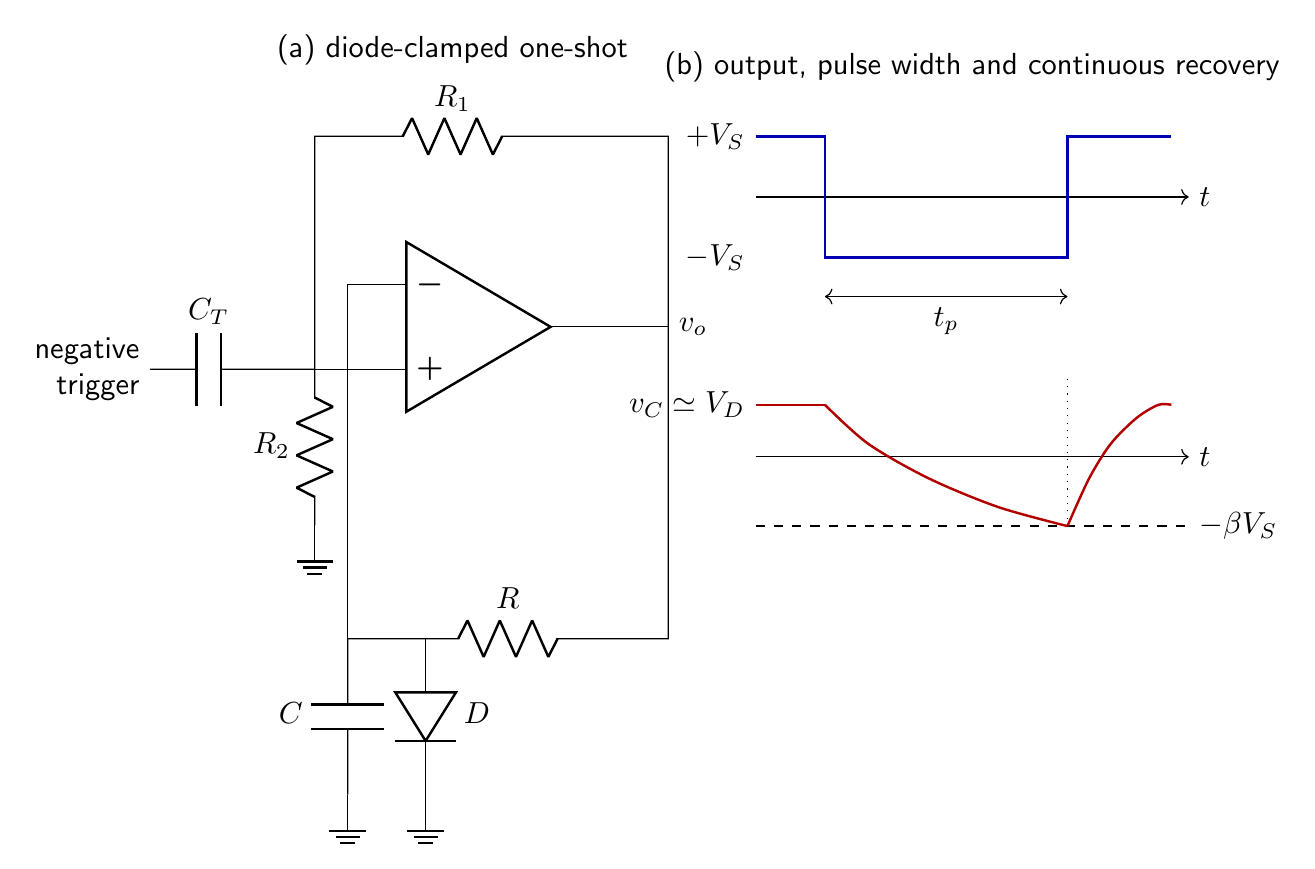
The monostable uses the same positive-feedback divider but adds a diode clamp to make one state stable. Consider a circuit whose quiescent output is $+V_S$. A timing resistor connects the output to the inverting-input node, and a capacitor connects that node to ground. A diode clamps positive timing-node voltage near $V_D$ in the quiescent state. Thus $v_-\simeq V_D$ while $v_+=+\beta V_S$; the high state is stable when $V_D<\beta V_S$.
A sufficiently negative trigger capacitively applied to the non-inverting summing node momentarily makes $v_+<v_-=V_D$ and switches the output to $-V_S$. Because the trigger is isolated from the timing node, the capacitor retains its pre-trigger voltage $v_C(0)=V_D$. The diode is then reverse biased and the capacitor approaches $-V_S$:
\[v_C(t)=-V_S+(V_D+V_S)e^{-t/RC}.\]During this temporary low-output state, the non-inverting threshold is $-\beta V_S$. The output returns high when $v_C=-\beta V_S$. Hence
\[-\beta V_S=-V_S+(V_D+V_S)e^{-t_p/RC},\]so the low-going output-pulse width is
\[\boxed{t_p=RC\ln\!\left[ \frac{V_S+V_D}{(1-\beta)V_S}\right].}\]For an ideal clamp $V_D=0$,
\[\boxed{t_p=RC\ln\!\left(\frac{1}{1-\beta}\right).}\]When the output returns to $+V_S$, capacitor continuity keeps $v_C=-\beta V_S$ at that instant. It then rises exponentially toward $+V_S$ until the diode conducts at $V_D$ and clamps it. The recovery trajectory is
\[v_C(t)=V_S-(1+\beta)V_Se^{-t/RC},\]where recovery time is measured from the low-to-high output transition. Setting $v_C(t_r)=V_D$ gives
\[\boxed{t_r=RC\ln\!\left[ \frac{(1+\beta)V_S}{V_S-V_D}\right].}\]The trigger must be shorter than the intended output pulse or coupled so that it does not hold the comparator in the temporary state.
Retriggering and recovery
A non-retriggerable monostable ignores triggers during the temporary state, whereas a retriggerable one restarts or extends its timing interval. The behavior depends on how the trigger is coupled and whether it resets the capacitor voltage. Recovery time is the interval after the output pulse during which the clamp and timing capacitor return sufficiently close to their quiescent values for the next pulse to have the specified width.
If a trigger arrives before recovery is complete, the pulse begins from a capacitor voltage different from $V_D$. Replacing $V_D$ by the actual $v_C(0)$ in the exponential solution predicts the width error. A precision one-shot isolates the trigger after initiation and provides a low-impedance recovery path when a short dead time is required.
Trigger amplitude must cross the active threshold but remain within the op amp’s permitted differential and common-mode input ranges. A differentiating input network can convert an input edge into a short trigger; a diode can suppress the unwanted polarity.
Nonideal timing and switching limits
The simple formulas assume constant, symmetric output levels, instantaneous transitions, an ideal capacitor and no input current. With $V_{OH}\ne-V_{OL}$, each interval must be derived from
\[v_C(t)=V_{\infty}+[v_C(0)-V_{\infty}]e^{-t/RC}\]using the actual asymptote and actual divider threshold. Bias current through a large $R$ changes the capacitor’s asymptotic voltage. Leakage becomes important for long periods. Output saturation recovery and slew rate add switching delays, while resistor and capacitor tolerances directly alter time intervals.
For the symmetric astable,
\[\frac{\Delta T}{T}\simeq\frac{\Delta R}{R}+\frac{\Delta C}{C} +\frac{2\Delta\beta}{(1-\beta^2)\ln[(1+\beta)/(1-\beta)]}.\]This shows that threshold-divider uncertainty can be as important as $RC$ tolerance, particularly when $\beta$ is close to unity. Supply changes cancel from the ideal symmetric period because both charging asymptotes and thresholds scale with $V_S$; output asymmetry and diode drops destroy that exact cancellation.
Film or C0G capacitors give low leakage and dielectric absorption but limited capacitance. Electrolytic capacitors permit long intervals at the cost of leakage, broad tolerance and polarity constraints. With very large $R$, op-amp bias current can become comparable to the intended timing current and invalidate the ideal logarithmic law.
The trajectories may be viewed in the $(v_o,v_C)$ plane. Output occupies one of two nearly horizontal branches while $v_C$ moves toward that branch’s asymptotic voltage. Reaching a threshold causes rapid transfer to the other output branch; capacitor continuity prevents a horizontal jump in $v_C$. An astable therefore traces a closed cycle, a bistable remains at either fixed branch, and a monostable makes one excursion before returning to its sole attracting branch.
Trigger specifications include polarity, minimum amplitude, minimum width and permitted repetition rate. Amplitude must exceed the active threshold with allowance for noise and offset. Width must complete switching but must not hold the timing input after regeneration. Repetition rate must leave the required recovery interval unless the circuit is expressly designed to retrigger.
A measured timing interval should be taken between output transition instants, while the capacitor trace verifies the assumed initial value, asymptote and threshold. This separates RC-law error from propagation delay.
Preparation questions
- Explain the number of stable states in bistable, monostable and astable multivibrators.
- Derive the period of the symmetric op-amp astable from the capacitor charging equation.
- Obtain the duty cycle when separate resistors control the high and low intervals.
- Derive the pulse width of the diode-clamped monostable including a nonzero clamp voltage.
- Explain retriggerable and non-retriggerable one-shot operation.
- Re-derive astable timing for unequal output limits $V_{OH}$ and $V_{OL}$.


Discussion