

29 Jun 2025
Op-Amp Square-Wave and Triangular-Wave Generators
Schmitt relaxation oscillators, integrator-comparator generators, frequency, amplitude, duty cycle and waveform limitations.
Op-amp waveform generators combine regenerative switching with controlled capacitor charging. A one-op-amp relaxation oscillator provides a square output and an exponentially varying capacitor voltage. A Schmitt trigger followed by an active integrator provides simultaneous square and approximately linear triangular outputs. The switching thresholds determine amplitude, while the capacitor charging law determines frequency.
Output limits are initially taken as $V_{OH}=+V_S$ and $V_{OL}=-V_S$. A positive-feedback divider establishes the Schmitt fraction
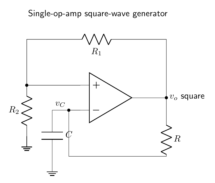
\[\beta_E=\frac{R_2}{R_1+R_2},\qquad 0<\beta_E<1,\]and thresholds $\pm\beta_E V_S$. The subscript $E$ identifies the divider ratio of the one-op-amp exponential generator; it must not be confused with the summing-network ratio $\beta_T$ introduced for the two-op-amp triangular generator. All polarities below follow the time-domain sign convention of the drawn circuits.
Single-op-amp square-wave generator
Connect the non-inverting input to $\beta v_o$. Connect a capacitor $C$ from the inverting input to ground and a resistor $R$ from the output to the inverting input. This is a Schmitt trigger whose comparison input is the capacitor voltage.
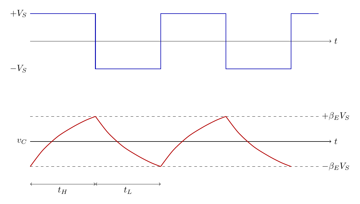
Immediately after the output switches high, capacitor continuity gives
\[v_C(0)=-\beta_E V_S.\]The capacitor then charges toward $+V_S$:
\[v_C(t)=V_S-(1+\beta_E)V_Se^{-t/RC}.\]At $v_C=+\beta_E V_S$ the comparator switches low. The high-state interval is
\[t_H=RC\ln\!\left(\frac{1+\beta_E}{1-\beta_E}\right).\]The negative interval is equal, so
\[\boxed{T=2RC\ln\!\left(\frac{1+\beta_E}{1-\beta_E}\right), \qquad f=\frac{1}{2RC\ln[(1+\beta_E)/(1-\beta_E)]}.}\]The output has levels $\pm V_S$ and ideal duty cycle $50\%$. The capacitor waveform lies between $\pm\beta_E V_S$ but consists of exponential arcs. It should not be called triangular merely because only a small central portion may look approximately straight.
Schmitt-trigger and integrator generator
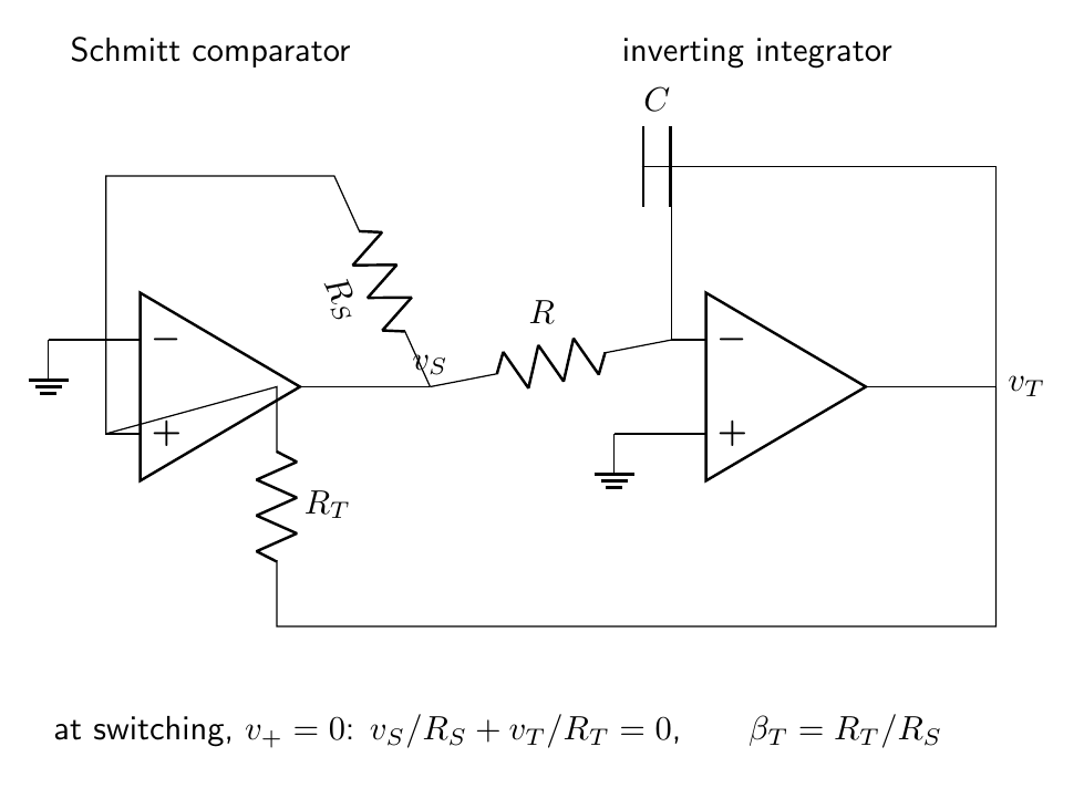
For a more accurate triangular waveform, use two op amps. The first is a non-inverting Schmitt comparator with output $v_S=\pm V_S$ and its inverting input at zero. Its non-inverting summing node is connected to $v_S$ through $R_S$ and to the integrator output $v_T$ through $R_T$. The second op amp is an inverting integrator with input resistor $R$ and feedback capacitor $C$. Since comparator input current is zero, switching occurs at $v_+=0$, where
\[\frac{v_S}{R_S}+\frac{v_T}{R_T}=0.\]Define the threshold ratio
\[\beta_T=\frac{R_T}{R_S}.\]The triangle thresholds are consequently $v_T=-\beta_T v_S$: for $v_S=+V_S$ the active threshold is $-\beta_T V_S$, while for $v_S=-V_S$ it is $+\beta_T V_S$.
For an ideal integrator,
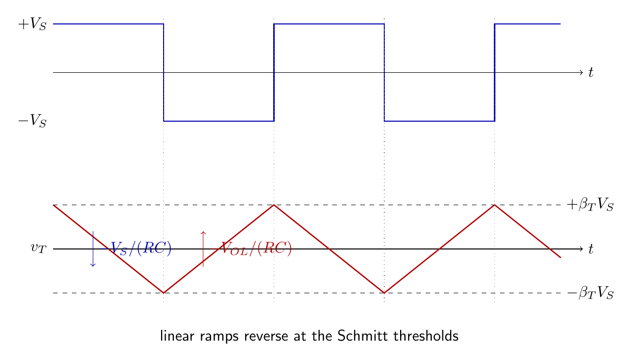
\[\boxed{\frac{dv_T}{dt}=-\frac{v_S}{RC}.}\]When $v_S=+V_S$, the triangular voltage decreases at constant slope $-V_S/(RC)$. It starts at $+\beta_T V_S$, the threshold that caused the preceding low-to-high transition, and travels to $-\beta_T V_S$. Therefore
\[t_H=\frac{2\beta_T V_S}{V_S/(RC)}=2\beta_T RC.\]When $v_S=-V_S$, the slope is $+V_S/(RC)$ and the return interval is identical. Hence
\[\boxed{T=4\beta_T RC, \qquad f=\frac{1}{4\beta_T RC}.}\]The ideal peak values are
\[\boxed{V_{S,\mathrm{pk}}=V_S,\qquad V_{T,\mathrm{pk}}=\beta_T V_S.}\]The square-wave amplitude cancels from the period because it scales both the integration slope and the switching thresholds. This cancellation relies on the same output levels setting both quantities.
The closed loop has a transparent state description. During each interval $v_S$ is constant, so $v_T$ evolves linearly. At a threshold the comparator changes $v_S$ discontinuously in the ideal model, while capacitor continuity keeps $v_T$ fixed. The new square level reverses $dv_T/dt$ and directs the trajectory toward the opposite threshold. These two linear flows joined by two switching surfaces form a stable limit cycle.
Unequal output levels
Real op amps may have $V_{OH}\ne -V_{OL}$. For the summing-node topology just defined, the threshold belonging to a given output state is the opposite-polarity value $v_T=-\beta_T v_o$. Thus the triangle descends from $-\beta_T V_{OL}$ to $-\beta_T V_{OH}$ while the output is high. With the integrator driven by the same output, the high-state duration is
\[t_H=RC\frac{\beta_T(V_{OH}-V_{OL})}{V_{OH}},\]whereas the low-state duration is
\[t_L=RC\frac{\beta_T(V_{OH}-V_{OL})}{-V_{OL}}.\]Thus
\[T=\beta_T RC(V_{OH}-V_{OL}) \left(\frac1{V_{OH}}-\frac1{V_{OL}}\right),\]and the high-output duty ratio is
\[\boxed{D=\frac{t_H}{t_H+t_L}= \frac{-V_{OL}}{V_{OH}-V_{OL}}.}\]Symmetric levels recover $D=1/2$ and $T=4\beta_T RC$. This derivation also shows why supply or load asymmetry produces duty-cycle error.
Duty-cycle and frequency control
In the one-op-amp exponential generator, separate diode-resistor charging paths give
\[t_H=R_HC\ln\!\left(\frac{1+\beta_E}{1-\beta_E}\right),\qquad t_L=R_LC\ln\!\left(\frac{1+\beta_E}{1-\beta_E}\right).\]In the integrator generator, different current magnitudes can be selected for the two square-wave polarities. If the currents are constant magnitudes $I_H$ and $I_L$, the triangular excursion is $\Delta V_T=V_{T+}-V_{T-}$ and
\[t_H=\frac{C\Delta V_T}{I_H},\qquad t_L=\frac{C\Delta V_T}{I_L}.\]Independent control of both currents changes duty cycle; scaling both by the same factor changes frequency without changing duty cycle. Precision current sources make the slopes less dependent on output swing than a simple input resistor.
Comparator with triangular input as a pulse-width modulator
A triangular voltage compared with a dc control $V_C$ produces a rectangular signal whose duty cycle depends on $V_C$. For a triangle that rises and falls linearly between $-V_T$ and $+V_T$, and a comparator high condition $v_T<V_C$, the fraction of a full period spent high is
\[\boxed{D=\frac12\left(1+\frac{V_C}{V_T}\right), \qquad -V_T\le V_C\le V_T.}\]Outside this range the output remains in one state. Reversing comparator polarity changes $D$ to $1-D$. This establishes the connection between triangular-wave generation and analog pulse-width modulation.
Harmonic content
For a symmetric square wave of peak $V_S$ and zero mean,
\[v_S(t)=\frac{4V_S}{\pi}\left( \sin\omega t+\frac{\sin3\omega t}{3}+ \frac{\sin5\omega t}{5}+\cdots\right).\]Only odd harmonics occur in the ideal $50\%$ waveform. Duty-cycle error introduces even harmonics and a dc component. A symmetric triangular wave of peak $V_T$ has, up to a choice of time origin,
\[v_T(t)=\frac{8V_T}{\pi^2}\left( \sin\omega t-\frac{\sin3\omega t}{3^2}+ \frac{\sin5\omega t}{5^2}-\cdots\right).\]Its harmonics fall as $1/n^2$, faster than the square wave’s $1/n$. Rounded triangle corners and finite square-wave transition time suppress higher harmonics further.
The ideal rms values are $V_{S,\mathrm{rms}}=V_S$ and $V_{T,\mathrm{rms}}=V_T/\sqrt3$. Hence the square-wave crest factor is unity and the triangle crest factor is $\sqrt3$. Measurements of rms value, dc component and even-harmonic content provide sensitive tests of symmetry and duty cycle.
Practical waveform accuracy
The square transition is limited by slew rate and saturation recovery. If the output changes by $\Delta V_o$, the transition time obeys $t_r\gtrsim\Delta V_o/\mathrm{SR}$. The integrator requires enough gain-bandwidth product to maintain a virtual summing node at the fundamental and relevant harmonics. Input offset and bias current add a dc term to $dv_T/dt$, making positive and negative slopes unequal and shifting the triangle’s mean value.
An ideal integrator has infinite dc gain and can drift into saturation. A large resistor $R_P$ placed in parallel with $C$ provides dc negative feedback. It changes the transfer function to a practical integrator,
\[\frac{V_T(s)}{V_S(s)}=-\frac{R_P/R}{1+sR_PC},\]which approximates $-1/(sRC)$ only when $\omega R_PC\gg1$. The condition should hold comfortably at the generated frequency.
With finite $R_P$, a constant square input produces a weak exponential rather than an exact ramp:
\[v_T(t)=v_{T,\infty}+[v_T(0)-v_{T,\infty}]e^{-t/(R_PC)}, \qquad v_{T,\infty}=-\frac{R_P}{R}v_S.\]If each half-period is much shorter than $R_PC$, first-order expansion of the exponential recovers the slope $-v_S/(RC)$. This supplies a direct criterion for acceptable triangle curvature.
Capacitor dielectric absorption, leakage, output-current limits, comparator delay and resistor tolerance perturb frequency and linearity. The triangle slope magnitude $V_S/(RC)$ must not demand an integrator output slew rate beyond its specification. Buffering the outputs prevents load-induced changes in $V_S$ and therefore in thresholds and timing.
Design example
Design a two-op-amp generator for $f=1.00\,\mathrm{kHz}$ with triangle peak $2.5\,\mathrm{V}$ and square peak $10.0\,\mathrm{V}$. Then
\[\beta_T=\frac{2.5}{10.0}=0.25.\]The summing network requires $R_T/R_S=\beta_T=0.25$; choose $R_S=40\,\mathrm{k\Omega}$ and $R_T=10\,\mathrm{k\Omega}$. Since
\[RC=\frac{1}{4\beta_T f}=1.00\,\mathrm{ms},\]$R=100\,\mathrm{k\Omega}$ and $C=10\,\mathrm{nF}$ are suitable. The triangle slope magnitude is $10^4\,\mathrm{V\,s^{-1}}$, well within many general-purpose op amps, while the required square-wave transition rate must be checked separately.
Frequency should be measured over many cycles, while slope linearity is tested separately on rising and falling ramps. Their difference reveals offset, output asymmetry or unequal current paths.
Preparation questions
- Derive the period of the single-op-amp square-wave generator and explain why its capacitor waveform is exponential.
- Starting from the ideal-integrator equation, obtain the frequency and triangle amplitude of the two-op-amp generator.
- Derive the high and low intervals for unequal output limiting levels.
- Design a $20\,\mathrm{kHz}$ square-triangle generator with $\beta_T=0.2$ and $C=1\,\mathrm{nF}$.
- Explain how separate charging currents permit independent control of frequency and duty cycle.
- Derive the pulse-width-modulator duty ratio for a triangular carrier and dc control voltage.


Discussion