

21 Jun 2025
Three-Section RC Phase-Shift Oscillator
Exact loaded RC-network analysis, oscillation frequency, gain requirement, startup and practical frequency stability.
The RC phase-shift oscillator combines an inverting amplifier with a cascade of three resistor-capacitor sections. At one frequency the RC network contributes $180^\circ$ phase shift and the inverting amplifier contributes the remaining $180^\circ$, so the total loop phase is $360^\circ$. Three sections are used because one first-order RC section contributes less than $90^\circ$ at every finite frequency; a three-section network can provide $180^\circ$ with a finite, calculable attenuation.
The analysis below assumes equal components $R_1=R_2=R_3=R$ and $C_1=C_2=C_3=C$, negligible op-amp input current, small output resistance and an unsaturated op amp. Phasors follow $e^{j\omega t}$. Because the sections load one another, multiplying three isolated high-pass transfer functions is incorrect.
Circuit and feedback sign
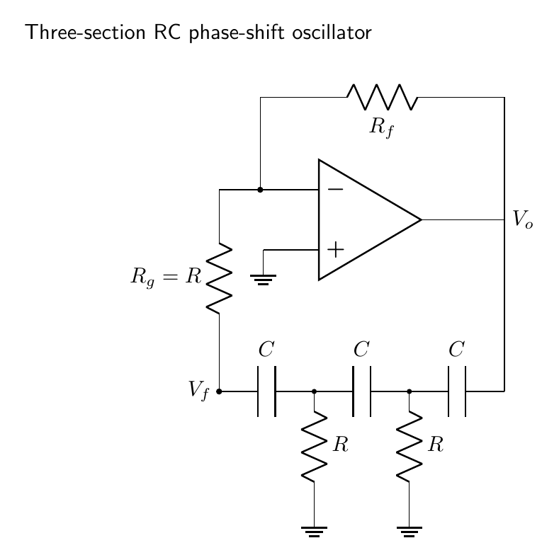
Let $V_o$ drive three series capacitors, with a resistor from each intermediate node to ground. The final network voltage $V_f$ is applied to an inverting amplifier. Define the passive-network transfer function
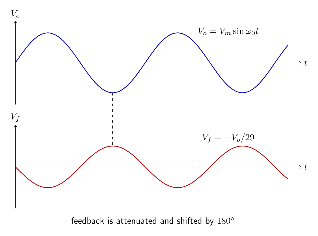
\[\beta(s)=\frac{V_f(s)}{V_o(s)}.\]The amplifier gain is $A=-K$, where $K>0$. The loop gain is therefore $L=-K\beta$. At oscillation $L(j\omega_0)=1$, which requires $\beta(j\omega_0)$ to be negative real and $K\lvert \beta\rvert=1$.
Exact transfer function of the loaded ladder
Write $x=sRC$. Nodal analysis of the three-section ladder gives
\[\boxed{\beta(s)=\frac{x^3}{x^3+6x^2+5x+1},\qquad x=sRC.}\]One way to obtain it is to label the successive node voltages $V_1,V_2,V_f$ and use the capacitor admittance $sC$. The nodal equations, after multiplying by $R$, are
\[(1+2x)V_1-xV_o-xV_2=0,\] \[-xV_1+(1+2x)V_2-xV_f=0,\] \[-xV_2+(1+x)V_f=0.\]Elimination of $V_1$ and $V_2$ yields the stated ratio. The coefficients $6$ and $5$ are direct consequences of interstage loading and would be absent from the erroneous product of three isolated sections.
The elimination can be displayed without skipping its determinant structure. The last equation gives
\[V_2=\frac{1+x}{x}V_f.\]Substitution in the middle equation gives
\[xV_1=\left(\frac{1+3x+x^2}{x}\right)V_f.\]Using both results in the first equation produces
\[x^3V_o=(x^3+6x^2+5x+1)V_f,\]which directly establishes $V_f/V_o$. For unequal components, each nodal admittance can instead be changed before taking the determinant; no assumption about isolated stages is then required.
At $s=j\omega$, put $u=\omega RC$. Then
\[\beta(j\omega)=\frac{-ju^3}{(1-6u^2)+j(5u-u^3)}.\]Multiplying numerator and denominator by the complex conjugate gives
\[\operatorname{Im}\beta= -\frac{u^3(1-6u^2)}{(1-6u^2)^2+(5u-u^3)^2}.\]The feedback is purely real at the nonzero frequency satisfying
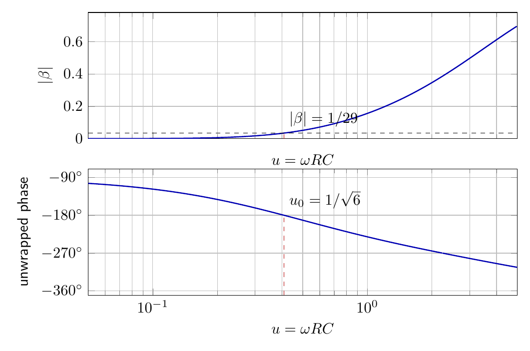
\[1-6u^2=0, \qquad u_0=\frac{1}{\sqrt6}.\]Therefore
\[\boxed{\omega_0=\frac{1}{RC\sqrt6},\qquad f_0=\frac{1}{2\pi RC\sqrt6}.}\]At $u_0=1/\sqrt6$,
\[5u_0-u_0^3=u_0\left(5-\frac16\right)=\frac{29u_0}{6},\]and hence
\[\boxed{\beta(j\omega_0)=-\frac1{29}.}\]The inverting-amplifier gain required by the Barkhausen magnitude condition is thus
\[\boxed{K=29.}\]For dependable startup the small-signal gain is chosen slightly larger than $29$; device nonlinearity or an explicit amplitude-control element then reduces the effective gain to $29$ in steady operation.
The phase discrimination can also be quantified. Let $D(u)=(1-6u^2)+j(5u-u^3)$. Since $\arg\beta=-\pi/2-\arg D$, differentiation at $u_0=1/\sqrt6$ gives
\[\left.\frac{d\arg\beta}{du}\right\rvert_{u_0}=-\frac{72}{29}.\]If the amplifier contributes a small additional phase $\delta\phi_A$, the phase condition yields
\[\boxed{\delta u\simeq\frac{29}{72}\,\delta\phi_A},\]with the signs defined by the loop-phase convention. This makes finite op-amp phase an explicit frequency error, not merely a gain-bandwidth restriction.
Op-amp realization
For an ideal inverting op amp $K=R_f/R_g$. Choosing
\[\frac{R_f}{R_g}>29\]provides startup margin. The network termination must agree with the assumed ladder: the third shunt resistance is $R_g=R$ connected to the amplifier’s virtual-ground summing node. No additional shunt resistor is placed there; otherwise the termination would be $R\parallel R_g$ and the derived polynomial would not apply.
As a numerical design, take $C=10\,\mathrm{nF}$ and require $f_0=1.00\,\mathrm{kHz}$. Then
\[R=\frac{1}{2\pi f_0 C\sqrt6} =6.50\,\mathrm{k\Omega}.\]A standard $6.49\,\mathrm{k\Omega}$ resistor gives nearly $1\,\mathrm{kHz}$. The terminating input resistor must also be $R_g=6.49\,\mathrm{k\Omega}$. Taking $R_f=196\,\mathrm{k\Omega}$ gives $K=R_f/R_g=30.20$, about $4.1\%$ above the ideal minimum.
The op amp must also have adequate gain-bandwidth product. The noise gain can be appreciably greater than unity, and phase lag contributed by the op amp shifts the frequency at which the total loop phase is zero. A conservative design keeps $f_0$ well below the closed-loop bandwidth associated with the required gain.
At dc the capacitors are open, so the resistance presented to the inputs differs from the ac network that determines oscillation. A resistor at the non-inverting input, approximately equal to the dc Thevenin resistance at the inverting input, can reduce output offset due to matched bias currents. It does not cancel input offset voltage or bias-current mismatch.
Buffered and unbuffered sections
If ideal voltage followers were inserted between the three sections, each isolated section would have
\[H_1(s)=\frac{sRC}{1+sRC},\]and the cascade response would be $H_1^3$. The phase condition would require each section to contribute $60^\circ$, giving $\omega RC=\tan30^\circ=1/\sqrt3$ and attenuation $(1/2)^3=1/8$. These values are sometimes applied incorrectly to an unbuffered ladder.
The actual circuit has no followers, so downstream current changes every upstream node voltage. It therefore has $\omega RC=1/\sqrt6$ and attenuation $1/29$. “Three identical sections” does not imply “three independent transfer functions”; the physical buffering and termination decide which formula applies.
For range switching, all three capacitors may be changed together while the resistors remain equal, or all three resistors may be switched as a matched set. Changing one element alone destroys equality and invalidates the simple frequency formula. Ganged components must track closely enough to preserve both phase distribution and feedback attenuation.
Startup transient and steady waveform
At switch-on, the component of noise close to $f_0$ is preferentially reinforced. If the loop magnitude is $1+\epsilon$ per effective traversal, the early envelope grows approximately exponentially. A simple cycle-to-cycle model is
\[a_{n+1}=(1+\epsilon)a_n, \qquad a_n=a_0(1+\epsilon)^n\simeq a_0e^{n\epsilon}.\]Once the output approaches the nonlinear region, gain compression stops growth. Hard saturation clips the peaks and injects odd harmonics. The RC network attenuates these harmonics, but low-distortion service requires a smoother amplitude-control method or only a small excess gain.
Unequal components and design limitations
For unequal $R_i,C_i$, the oscillation condition must be obtained from the actual network determinant. It is not legitimate to replace $RC$ in the equal-component formula by an arbitrary average. Component tolerances perturb both phase and attenuation, so the frequency and gain conditions shift together.
For the equal-component frequency,
\[f_0=(2\pi\sqrt6\,RC)^{-1},\]small variations give
\[\boxed{\frac{\Delta f_0}{f_0}\simeq-\frac{\Delta R}{R}-\frac{\Delta C}{C}.}\]If the three resistors and capacitors vary independently, exact sensitivity follows from the full characteristic polynomial rather than this common-scaling result. Temperature-stable capacitors and matched resistor networks reduce drift.
The principal limitations are the large amplifier gain requirement, loading errors, op-amp finite bandwidth and slew rate, component spread, output clipping and limited high-frequency operation. At very low frequency, large resistor values increase noise and bias-current error, while large electrolytic capacitors have leakage and poor tolerance. The circuit is consequently most useful over the low-frequency and audio ranges.
For a sinusoidal output $v_o=V_p\sin\omega_0t$, the minimum slew rate is $\omega_0V_p$. The op amp must also supply current to the ladder. Since its first CR section directly loads the output, output resistance changes the effective first-section impedance and the characteristic polynomial. A follower after the oscillator isolates the external load, but not this internal loading already included in the exact derivation.
Frequency response about oscillation
The feedback magnitude is not sharply resonant. The oscillation frequency is selected primarily by phase. Around $u_0$, a perturbation $\Delta\phi$ from the amplifier changes the selected frequency by
\[\Delta\omega\simeq- \frac{\Delta\phi}{d(\arg\beta)/d\omega\rvert_{\omega_0}}.\]Thus additional amplifier phase lag causes frequency error. It may also increase the necessary gain because $\lvert \beta\rvert$ at the shifted frequency is different from $1/29$. These coupled phase and magnitude effects explain why measured circuits depart from the ideal component formula as $f_0$ approaches the op amp’s bandwidth limit.
A frequency measurement should be compared with the value calculated from measured, not nominal, components. The observed amplitude should remain below the slew-rate and output-current limits, and the three RC node voltages should display successive phase rotations without probe loading. A standard oscilloscope probe adds capacitance to a ladder node; a low-capacitance active probe or buffer is preferable when the added capacitance is not negligible compared with $C$.
Preparation questions
- Derive the transfer function of the loaded three-section CR ladder by nodal analysis.
- Show that $\omega_0RC=1/\sqrt6$ and $\beta(j\omega_0)=-1/29$.
- Explain why multiplying three isolated first-order transfer functions gives an incorrect result.
- Design a $2.0\,\mathrm{kHz}$ phase-shift oscillator for $C=4.7\,\mathrm{nF}$ and specify a practical amplifier gain.
- Discuss startup, amplitude stabilization and harmonic distortion in this oscillator.
- Explain how finite op-amp bandwidth changes both the oscillation frequency and minimum required gain.


Discussion