

23 Jun 2025
Wien-Bridge Oscillator and Amplitude Stabilization
Lead-lag bridge analysis, frequency and gain conditions, startup, nonlinear stabilization and distortion.
The Wien-bridge oscillator is a low-distortion RC sinusoidal oscillator. A series RC arm and a parallel RC arm form a frequency-selective positive-feedback network; a non-inverting amplifier supplies the gain. At the balance frequency the network has zero phase shift and an attenuation of one third, so the ideal amplifier gain is three. Reliable operation additionally requires a mechanism that gives gain greater than three during startup and brings it smoothly to three at the desired amplitude.
Phasors use $e^{j\omega t}$. The voltage returned to the non-inverting input is $V_f=\beta V_o$. Negative feedback around the op amp establishes the non-inverting gain $A=1+R_f/R_g$ when the stabilizing elements behave linearly.
Wien lead-lag network
Let the series arm from $V_o$ to $V_f$ be $Z_s=R_1+1/(sC_1)$ and the shunt arm be $Z_p=R_2/(1+sR_2C_2)$. The feedback fraction is
\[\beta(s)=\frac{Z_p}{Z_s+Z_p}.\]For the common equal-component case $R_1=R_2=R$ and $C_1=C_2=C$, define $x=sRC$. Straight simplification gives
\[\boxed{\beta(s)=\frac{x}{x^2+3x+1}.}\]At $s=j\omega$ and $u=\omega RC$,
\[\beta(j\omega)=\frac{ju}{1-u^2+j3u}.\]Multiplication by the complex conjugate yields
\[\beta= \frac{3u^2+j u(1-u^2)}{(1-u^2)^2+9u^2}.\]The imaginary part vanishes at the nonzero frequency $u=1$. Therefore
\[\boxed{\omega_0=\frac1{RC},\qquad f_0=\frac1{2\pi RC}, \qquad \beta(j\omega_0)=\frac13.}\]Since this feedback is positive and has zero phase at $\omega_0$, the loop-gain condition $A\beta=1$ requires
\[\boxed{A=3.}\]For the ideal non-inverting amplifier,
\[1+\frac{R_f}{R_g}=3, \qquad \boxed{R_f=2R_g.}\]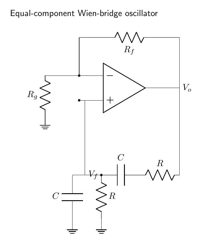
General unequal-component balance
For arbitrary positive $R_1,R_2,C_1,C_2$, the zero-phase frequency is
\[\boxed{\omega_0=\frac{1}{\sqrt{R_1R_2C_1C_2}}}.\]At this frequency the real feedback fraction is
\[\boxed{\beta_0= \frac{R_2C_1}{R_1C_1+R_2C_1+R_2C_2}},\]so the required amplifier gain is
\[\boxed{A_0=1+\frac{R_1}{R_2}+\frac{C_2}{C_1}.}\]The equal-component values $\beta_0=1/3$ and $A_0=3$ follow immediately. These expressions show that changing only one component alters both frequency and attenuation; tuning arrangements therefore use ganged resistors or capacitors to preserve the gain condition over a range.
Expanding the impedance-divider denominator and separating real and imaginary parts shows that zero phase is equivalent to
\[1-\omega^2R_1R_2C_1C_2=0.\]At this frequency the reactive terms cancel in the ratio even though current continues through both capacitors. Substitution gives the real $\beta_0$ above. The bridge is therefore balanced in phase, not open-circuited; the non-inverting input samples a finite output fraction.
Frequency response
For equal components,
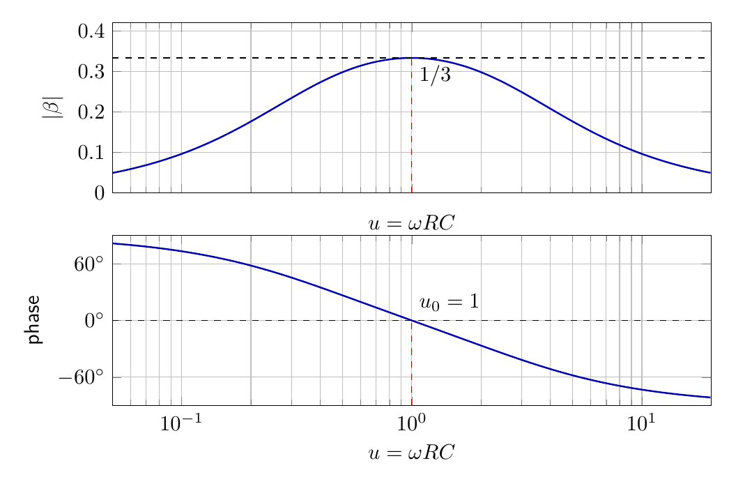
\[\lvert \beta\rvert=\frac{u}{\sqrt{(1-u^2)^2+9u^2}},\]and
\[\arg\beta=\tan^{-1}\!\left(\frac{1-u^2}{3u}\right),\]with the quadrant selected from the real and imaginary parts. Below $\omega_0$ the feedback leads; above $\omega_0$ it lags. Only at $\omega_0$ is its phase zero. Its magnitude reaches the maximum $1/3$ there, so a gain of three gives unity loop magnitude only at the balance frequency.
The local phase slope follows from the analytical phase:
\[\left.\frac{d\arg\beta}{du}\right\rvert_{u=1}=-\frac23, \qquad u=\omega RC.\]If the amplifier adds a small phase $\delta\phi_A$, the phase condition gives $\delta u\simeq(3/2)\delta\phi_A$. The modest slope explains why a Wien network cannot equal a high-$Q$ crystal in frequency stability and gives a quantitative reason to keep op-amp phase error small at $f_0$.
Startup and the need for automatic gain control
If $A<3$, noise components decay and oscillation does not start. If an exactly linear loop had $A=3$, its amplitude would be set by an initial condition and would not be robust to loss changes. If $A>3$ with no amplitude control, the sinusoid grows until the op amp clips. The clipped waveform contains strong harmonics and no longer realizes the intended low-distortion oscillator.
The appropriate gain characteristic satisfies
\[A(0)>3,\qquad A(V_{o,\mathrm{rms}})=3, \qquad \frac{dA}{dV_{o,\mathrm{rms}}}<0\]near the steady amplitude. The gain-control time constant should be long compared with one oscillation period so that it responds mainly to the envelope rather than modulating each cycle.
Tungsten-lamp stabilization
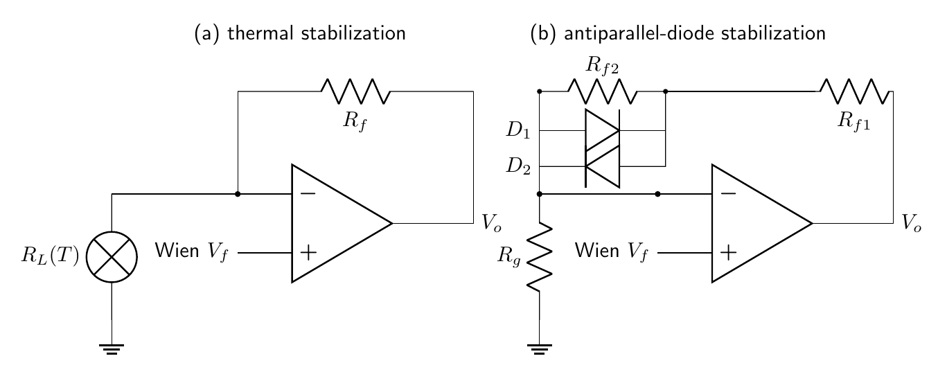
A small incandescent lamp can replace $R_g$ in the negative-feedback divider. Its filament has a positive temperature coefficient. At switch-on the filament is cold, its resistance is low, and
\[A=1+\frac{R_f}{R_{\text{lamp}}}>3.\]As the output grows, lamp power heats the filament, $R_{\text{lamp}}$ rises, and the gain decreases toward three. Thermal inertia averages the power over many cycles, producing smooth control and low distortion.
At equilibrium the required hot resistance is $R_{\text{lamp,hot}}=R_f/2$. The output amplitude is not fixed solely by this relation; it is the amplitude whose dissipated lamp power raises the filament to that resistance. Supply voltage, lamp thermal environment and load therefore influence amplitude.
Diode and JFET stabilization
Back-to-back diodes placed across part of $R_f$ remain nearly open for small signals, giving $A>3$. At larger output they conduct on alternate half cycles, shunt part of $R_f$ and reduce gain. The method is simple but the within-cycle switching generates more distortion than a lamp. Series resistors soften conduction.
A JFET operated in its ohmic region can act as a voltage-controlled resistor in the gain-setting network. A rectifier and low-pass filter derive a control voltage from the output amplitude. This is an explicit automatic-gain-control loop and can provide a predictable amplitude over a broad tuning range, provided the FET signal voltage remains small enough for approximately resistive operation.
Dynamics of amplitude control
Let the effective amplifier gain be $A(a)$ and define the loop excess at balance by $m(a)=A(a)/3-1$. For a slowly varying amplitude,
\[\frac{da}{dt}\simeq\lambda m(a)a,\]where $\lambda$ depends on the selective-network bandwidth. A steady amplitude satisfies $A(a_s)=3$. Linearizing gives
\[\frac{d(\delta a)}{dt}\simeq \lambda a_s\left.\frac{dm}{da}\right\rvert_{a_s}\delta a,\]so stable recovery requires $dm/da<0$. If control responds within each cycle, gain becomes an instantaneous function of voltage and creates harmonics. If it responds extremely slowly, distortion can be low but startup overshoot and recovery after load changes are prolonged. Lamp thermal inertia naturally places the control bandwidth well below the oscillation frequency.
Harmonics produced by limiting do not satisfy the same bridge balance. For the $n$th harmonic of an equal-component network,
\[\lvert \beta(n)\rvert=\frac{n}{\sqrt{(1-n^2)^2+9n^2}},\]which falls with harmonic order. The bridge filters nonlinear products, although it cannot remove distortion already present strongly at the amplifier output.
Design example and nonideal effects
For $f_0=1.00\,\mathrm{kHz}$ and $C=10.0\,\mathrm{nF}$,
\[R=\frac{1}{2\pi f_0C}=15.9\,\mathrm{k\Omega}.\]Using $15.8\,\mathrm{k\Omega}$ gives approximately $1.007\,\mathrm{kHz}$. A linear trial circuit with $R_g=10\,\mathrm{k\Omega}$ and $R_f=20.5\,\mathrm{k\Omega}$ has gain $3.05$, sufficient for startup but requiring a nonlinear element to lower the effective gain at the final amplitude.
For common changes of $R$ and $C$,
\[\frac{\Delta f_0}{f_0}\simeq -\frac{\Delta R}{R}-\frac{\Delta C}{C}.\]Finite op-amp open-loop gain changes the closed-loop gain and phase. Slew-rate limiting occurs when
\[2\pi f_0V_{o,\mathrm{pk}}>\mathrm{SR},\]and produces a triangular-looking output. Output-current limitation, bridge loading and the op amp’s input common-mode range also restrict amplitude. A buffer may be used after the oscillator so that load changes do not perturb the bridge. Resistor thermal noise and op-amp noise cause phase fluctuations; component temperature coefficients and aging cause long-term frequency drift.
The Wien network is less selective than a high-$Q$ crystal resonator, but its continuous tuning, simple RC construction and low distortion under smooth gain control make it important in audio-frequency generators.
For wide-range tuning, two equal resistors may be varied by a dual-gang control while the capacitors remain equal. Tracking error matters: the frequency depends on a geometric mean, while required gain changes according to $A_0=1+R_1/R_2+C_2/C_1$. A fixed gain that is safe at one end may fail to start or overdrive the amplifier at the other, so automatic gain control must accommodate bridge-attenuation error over the entire range.
The output is commonly buffered before driving a low resistance. Without isolation, load current may alter output swing, distortion and the gain-control operating point. The bridge itself must see low source resistance and high receiving impedance so that its chosen $R$ and $C$ remain the dominant impedances.
When the equal resistors are scaled by a factor $k$ with capacitors fixed, frequency scales as $1/k$ but the ideal attenuation remains $1/3$. Scaling both capacitors similarly has the same property. This invariance is what permits ganged equal-component tuning without redesigning the nominal amplifier gain.
Measured gain should be referred to the fundamental component when distortion is appreciable.
Preparation questions
- Derive $\beta(s)=sRC/[(sRC)^2+3sRC+1]$ for the equal-component Wien network.
- Obtain the oscillation frequency and show that the non-inverting gain must be three.
- Derive the frequency and gain conditions for unequal $R_1,R_2,C_1,C_2$.
- Explain quantitatively how a tungsten lamp stabilizes amplitude.
- Compare lamp, diode and JFET amplitude control with respect to startup and distortion.
- Design a $5\,\mathrm{kHz}$ oscillator using $C=2.2\,\mathrm{nF}$ and estimate the minimum op-amp slew rate for a $10\,\mathrm{V}$ peak output.


Discussion