

13 Jul 2026
Study of Analogue-to-Digital and Digital-to-Analogue Converters
Aim
To study an analogue-to-digital converter and a digital-to-analogue converter and determine the step size and conversion error.
Apparatus
ADC/DAC trainer, regulated supply, function generator, CRO, digital multimeter, and patch cords.
Experimental arrangement
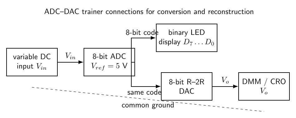
Theory
An analogue voltage can take any value in a continuous range, whereas a digital system uses a finite set of codes. Before conversion, an ADC samples the input and compares it with thresholds derived from a reference voltage. The sample is assigned to one of $2^n$ quantisation intervals and the interval number is delivered as an $n$-bit binary code.
For a unipolar $n$-bit ADC spanning 0 to $V_{ref}$, the ideal step size or one least significant bit is
\[q=\frac{V_{ref}}{2^n}.\]If the code is chosen by rounding to the nearest level, the ideal quantisation error is no greater than $q/2$. Practical offset, gain, differential-linearity, and settling-time errors add to this value.
An R-2R DAC sends binary-weighted currents from its resistor ladder to a summing node. For decimal code $D$ from 0 to $2^n-1$, the ideal unipolar output is
\[V_o=V_{ref}\frac{D}{2^n-1}.\]Thus the ADC maps voltage to code and the DAC maps that code back to a staircase approximation of the original voltage. Monotonicity means that increasing the input or code never produces a lower output.
Observations
For an 8-bit, $5$ V converter, $q=19.53$ mV.
| Input voltage (V) | ADC code | DAC output (V) | Error (mV) |
|---|---|---|---|
| 0.50 | 00011010 | 0.508 | 8 |
| 1.00 | 00110011 | 0.996 | 4 |
| 2.50 | 10000000 | 2.510 | 10 |
| 4.00 | 11001101 | 4.000 | 0 |
Calculation
For $n=8$ and $V_{ref}=5$ V,
\[q=\frac{5}{2^8}=19.53\,\text{mV}.\]For $V_{in}=0.50$ V, the nearest code is
\[D=\frac{0.50}{0.01953}=25.6\approx26=00011010_2.\]The corresponding ideal DAC output is
\[V_o=5\frac{26}{255}=0.510\,\text{V},\]close to the observed 0.508 V. The observed error is 8 mV, which is smaller than one LSB.
Result
The ADC gives a monotonic binary code and the DAC reconstructs the input voltage with an error of about one least-significant bit or less.
Viva Questions
- What is resolution? The analogue voltage represented by one digital count.
- What is quantisation error? The difference between the input voltage and the nearest available digital level.
- What is monotonicity? The output does not decrease when the input code increases.


Discussion