

13 Jul 2026
Hartley Oscillator and Determination of Oscillation Frequency
Aim
To construct a Hartley oscillator and study the dependence of its frequency on the inductance and capacitance of the tuned circuit.
Apparatus
Transistor oscillator kit, two coupled inductors or tapped coil, capacitor, DC supply, CRO, frequency counter, and connecting leads.
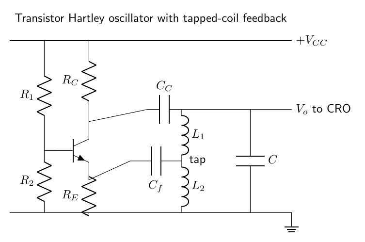
Experimental arrangement
Theory
An oscillator converts energy from a DC supply into a periodic signal without an external periodic input. A small noise voltage starts the process. The amplifier increases this voltage and positive feedback returns part of the output in phase with the original disturbance. A steady sinusoid is obtained when the Barkhausen conditions are satisfied: the total phase shift is $0$ or $2\pi$ and the loop-gain magnitude settles to unity.
In the Hartley oscillator, $L_1$, $L_2$, and $C$ form the resonant tank. When the capacitor discharges, current builds magnetic energy in the inductors; when the magnetic field collapses, the induced emf recharges the capacitor with opposite polarity. Ideally this exchange occurs at the natural frequency of the tank. The transistor replaces the energy lost in the coil resistance and load.
Because the two coil sections are magnetically coupled, their effective series inductance is
\[L_{eq}=L_1+L_2+2M,\]where the plus sign applies when the windings are series aiding. The oscillation frequency is therefore
\[f=\frac{1}{2\pi\sqrt{(L_1+L_2+2M)C}},\]The tapped inductive divider determines the feedback fraction. Reversing one coil connection changes the feedback phase and prevents sustained oscillation.
Observations
| $C$ (nF) | Observed frequency (kHz) |
|---|---|
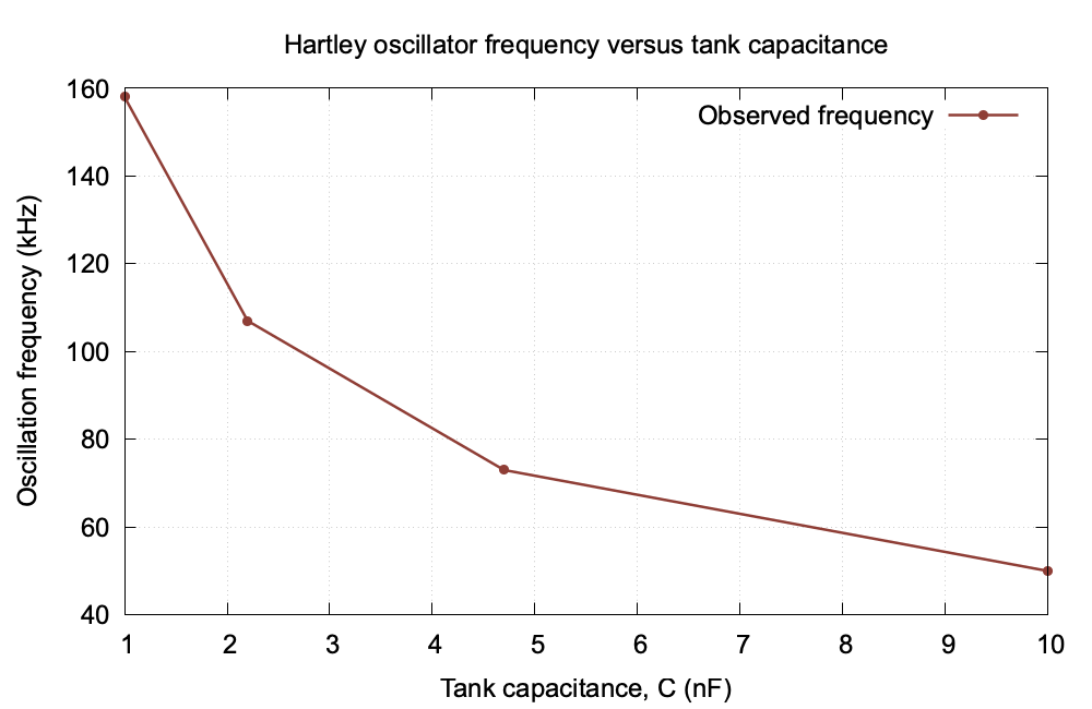
| 1.0 | 158 |
| 2.2 | 107 |
| 4.7 | 73 |
| 10.0 | 50 |
Graph
Calculation
Using $C=1.0$ nF and $f=158$ kHz, the effective tank inductance is
\[L_{eq}=\frac{1}{(2\pi f)^2C}=\frac{1}{[2\pi(158\times10^3)]^2(1.0\times10^{-9})}=1.01\,\text{mH}.\]With this inductance and $C=10$ nF,
\[f=\frac{1}{2\pi\sqrt{(1.01\times10^{-3})(10\times10^{-9})}}=50.1\,\text{kHz},\]which agrees with the observed 50 kHz.
Result
The circuit produces a nearly sinusoidal oscillation. The frequency decreases as the tank capacitance increases, in agreement with the LC resonance relation.
Viva Questions
- Why is a tapped coil used? It supplies the correct amount and phase of feedback.
- What is the Barkhausen condition? The loop gain must be unity and the total phase shift must be an integral multiple of $2\pi$.
- What determines the frequency? The effective inductance and capacitance of the tank circuit.


Discussion