

13 Jul 2026
Op-Amp Differentiator and Integrator
Aim
To study the waveforms produced by practical op-amp differentiator and integrator circuits.
Apparatus
741 op-amp, dual DC supply, resistors, capacitors, function generator, CRO, breadboard, and connecting wires.
Experimental arrangement
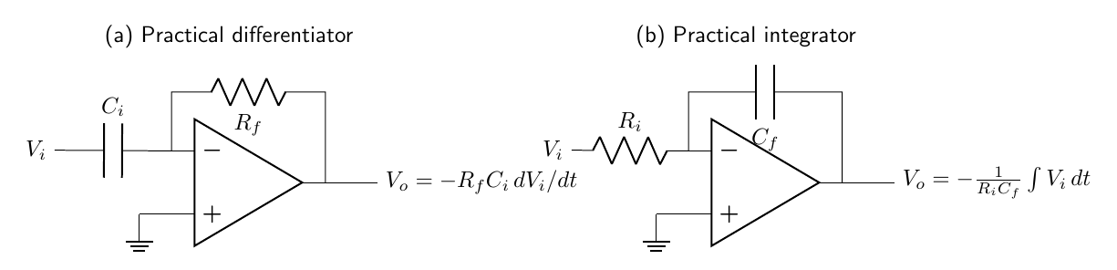
Theory
An operational amplifier produces $V_o=A(V_+-V_-)$, where the open-loop gain $A$ is very large. With negative feedback and an unsaturated output, only a minute input difference is needed, so $V_-\approx V_+$. Since the non-inverting terminal is grounded, the inverting node is at virtual ground. The op-amp input current is negligible, so Kirchhoff’s current law can be applied directly at this node.
For the differentiator, the capacitor current is $i=C_i\,dV_i/dt$. The same current passes through $R_f$, giving
\[V_o=-R_fC_i\frac{dV_i}{dt}.\]A constant input gives zero output, while the constant slopes of a triangular wave give two constant output levels. A square wave changes abruptly, so its edges produce positive and negative pulses. A practical differentiator includes frequency-limiting components to prevent excessive amplification of high-frequency noise.
For the integrator, the input current is $i=V_i/R_i$ and this charges the feedback capacitor. Since $i=-C_f\,dV_o/dt$,
\[V_o=-\frac{1}{R_iC_f}\int V_i\,dt+V_o(0).\]A square input therefore gives a triangular output. A resistor is normally placed in parallel with $C_f$ to limit the DC gain and prevent drift into saturation.
Observations
| Input waveform | Differentiator output | Integrator output |
|---|---|---|
| Square | Positive and negative spikes | Triangular waveform |
| Sine | Cosine-like waveform | Negative cosine-like waveform |
| Triangular | Square waveform | Parabolic segments |
Calculation
For a differentiator with $R_f=10$ k$\Omega$, $C_i=0.01\,\mu$F, and input slope $dV_i/dt=0.40$ V ms$^{-1}$,
\[V_o=-(10^4)(0.01\times10^{-6})(400)=-0.040\,\text{V}.\]For an integrator with $R_i=10$ k$\Omega$, $C_f=0.10\,\mu$F, and a constant $1$ V input applied for 1 ms,
\[\Delta V_o=-\frac{(1)(1\times10^{-3})}{(10^4)(0.10\times10^{-6})}=-1.0\,\text{V}.\]Result
The differentiator produces an output proportional to the rate of change of the input, while the integrator produces an output proportional to the time integral of the input.
Viva Questions
- Why is the op-amp called inverting here? The signal is applied to the inverting terminal and the non-inverting terminal is grounded.
- What limits a practical differentiator? High-frequency noise and the finite bandwidth of the op-amp.
- Why is a capacitor used at the input of an integrator? Its impedance causes the input current to be proportional to the time integral of voltage.


Discussion