

13 Jul 2026
V-I Characteristics and Holding Current of an SCR
Aim
To plot the anode characteristics of a silicon-controlled rectifier and determine its latching and holding currents.
Apparatus
SCR, regulated DC supply, gate-pulse supply, series resistor, load resistor, voltmeters, milliammeter, and connecting leads.
Experimental arrangement
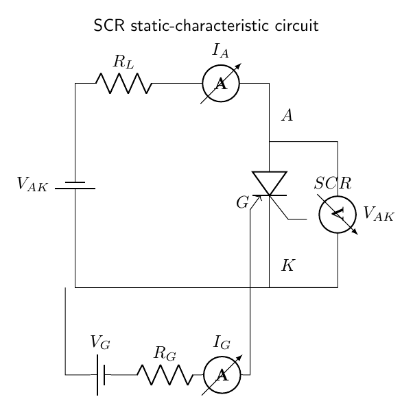
Theory
An SCR is a four-layer PNPN device with three junctions and terminals called anode, cathode, and gate. With the anode positive relative to the cathode, the outer junctions are forward biased but the central junction is reverse biased. The device therefore remains in the forward-blocking state and carries only leakage current.
The PNPN structure can be represented as mutually coupled PNP and NPN transistors. A positive gate current increases the NPN collector current, which drives the PNP transistor; the PNP collector current then reinforces the NPN base current. When the sum of current gains approaches unity, this regenerative feedback switches both transistor sections into conduction. The anode-cathode voltage collapses to the small on-state value.
After turn-on, the internal feedback supplies the required base currents and the gate no longer controls the device. The latching current $I_L$ is the minimum anode current required immediately after the gate signal is removed. The holding current $I_H$ is the lower current below which an already conducting SCR returns to the blocking state. A gate current reduces the required firing voltage but does not provide turn-off in a DC circuit.
Observations
| Gate current (mA) | Breakover / firing voltage (V) | On-state current (mA) |
|---|---|---|
| 0.0 | 42 | 0 |
| 0.5 | 28 | 12 |
| 1.0 | 18 | 18 |
| 1.5 | 12 | 24 |
The anode current falls to zero at approximately $I_H=8$ mA.
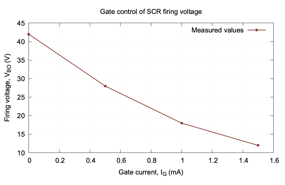
Graph
Calculation
Increasing the gate current from 0 to 1.5 mA reduces the firing voltage from 42 V to 12 V. The percentage reduction is
\[\frac{42-12}{42}\times100=71.4\%.\]On decreasing the anode current after firing, turn-off occurs at approximately $I_H=8$ mA. This is the measured holding current of the device.
Result
The SCR changes from forward blocking to conduction when triggered by the gate. The observed holding current is approximately $8$ mA.
Viva Questions
- How is an SCR turned on? By applying forward bias and a suitable gate pulse.
- How is it turned off in a DC circuit? The anode current must be reduced below the holding current.
- What is the difference between latching and holding current? Latching current maintains conduction just after triggering; holding current maintains an already established conduction state.


Discussion