

13 Jul 2026
Characteristics of a Unijunction Transistor and Relaxation Oscillator
Aim
To study the emitter characteristic of a unijunction transistor and observe its use in a relaxation oscillator.
Apparatus
UJT, regulated DC supply, variable emitter supply, resistors, capacitor, CRO, voltmeters, and milliammeter.
Experimental arrangement
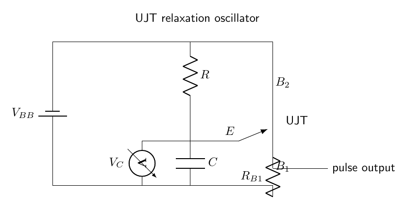
Theory
A UJT contains a lightly doped n-type bar with ohmic contacts $B_1$ and $B_2$ and one p-type emitter junction. With the emitter open, the inter-base resistance is $R_{BB}=R_{B1}+R_{B2}$. Applying $V_{BB}$ establishes a potential at the emitter junction equal to a fraction of the inter-base voltage. The intrinsic stand-off ratio is
\[\eta=\frac{R_{B1}}{R_{B1}+R_{B2}}.\]The emitter junction remains reverse biased until its voltage reaches the peak value
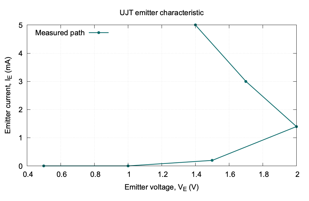
\[V_P=\eta V_{BB}+V_D,\]where $V_D$ is the forward drop of the emitter junction. At the peak point, holes injected into the n-type bar reduce $R_{B1}$. The emitter current then increases while the emitter voltage falls, producing the negative-resistance region between peak and valley points.
In the relaxation oscillator, the capacitor charges through $R$ as $V_C=V_{BB}(1-e^{-t/RC})$. When $V_C=V_P$, the UJT turns on and the capacitor discharges rapidly through $B_1$. When the emitter current falls below the valley current the UJT turns off and charging begins again. Neglecting the short discharge time,
\[T=RC\ln\left(\frac{1}{1-V_P/V_{BB}}\right),\qquad f=\frac1T.\]Observations
| Emitter voltage $V_E$ (V) | Emitter current $I_E$ (mA) |
|---|---|
| 0.5 | 0.0 |
| 1.0 | 0.0 |
| 1.5 | 0.2 |
| 2.0 | 1.4 |
| 1.7 | 3.0 |
| 1.4 | 5.0 |
The CRO shows a repeated saw-tooth waveform across the timing capacitor.
Graph
Calculation
The measured peak point is approximately $(V_P,I_P)=(2.0\,\text{V},1.4\,\text{mA})$. Using the peak and the last observed point, the mean dynamic resistance in the negative-resistance region is
\[r_d=\frac{\Delta V_E}{\Delta I_E}=\frac{1.4-2.0}{(5.0-1.4)\times10^{-3}}=-167\,\Omega.\]The negative sign is the defining feature of this region.
Result
The UJT exhibits a negative-resistance region after the peak point and produces a saw-tooth relaxation waveform when connected with a timing resistor and capacitor.
Viva Questions
- Why does the UJT show negative resistance? Carrier injection lowers the inter-base resistance after the peak point.
- What determines the oscillator frequency? Mainly the timing resistance, capacitance, and peak voltage.
- Why is the output saw-tooth shaped? The capacitor charges slowly and discharges rapidly through the UJT.


Discussion