

13 Jul 2026
Zener Diode Characteristics and Voltage Stabilisation
Aim
To plot the forward and reverse characteristics of a Zener diode and study its use as a shunt voltage stabiliser.
Apparatus
Zener diode, regulated DC supply, series resistor, load resistor, milliammeter, voltmeters, patch cords, and breadboard or electronics trainer.
Experimental arrangement
Theory
A p-n junction forms a depletion region and an internal electric field at the boundary between p-type and n-type material. In forward bias the external field lowers the junction barrier and the diode conducts strongly after its knee voltage. In reverse bias the barrier increases and only a small minority-carrier current flows until the electric field in the depletion layer becomes sufficiently large for breakdown.
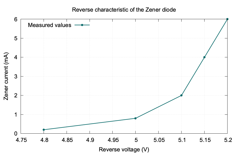
A Zener diode is heavily doped and manufactured to operate safely in this reverse-breakdown region. At lower breakdown voltages tunnelling is important; at higher voltages avalanche multiplication is important. In either case, once the knee is crossed, a large change in reverse current produces only a small change in terminal voltage. The local slope is represented by the dynamic resistance $r_Z=\Delta V_Z/\Delta I_Z$.
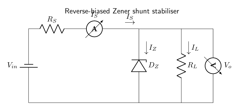
In the shunt regulator shown above, $R_S$ absorbs the difference between input and Zener voltage and limits the total current. Kirchhoff’s current law at the output node gives
For a stabiliser, the series current is
\[I_S=\frac{V_{in}-V_Z}{R_S},\]and
\[I_S=I_L+I_Z,\qquad V_L=V_Z.\]If $V_{in}$ rises or $I_L$ falls, the excess current is taken by the Zener, leaving $V_L$ nearly unchanged. Regulation fails if $I_Z$ falls below the knee current. The power condition $P_Z=V_ZI_Z<P_{Z,\max}$ must also be satisfied.
Observations
| Reverse voltage (V) | Zener current (mA) |
|---|---|
| 4.80 | 0.2 |
| 5.00 | 0.8 |
| 5.10 | 2.0 |
| 5.15 | 4.0 |
| 5.20 | 6.0 |
For $V_{in}=9$ V and $R_S=470\,\Omega$:
| Load current (mA) | Stabilised output (V) |
|---|---|
| 1.0 | 5.08 |
| 2.0 | 5.10 |
| 3.0 | 5.11 |
Graph
Calculation
For $V_{in}=9$ V, $V_Z=5.1$ V, and $R_S=470\,\Omega$,
\[I_S=\frac{9-5.1}{470}=8.30\,\text{mA}.\]At $I_L=3.0$ mA,
\[I_Z=I_S-I_L=8.30-3.00=5.30\,\text{mA},\]so $P_Z=V_ZI_Z=5.1(5.30\times10^{-3})=27.0$ mW. From the reverse-characteristic readings between 2 mA and 6 mA,
\[r_Z=\frac{5.20-5.10}{(6-2)\times10^{-3}}=25\,\Omega.\]Result
The Zener voltage is approximately $5.1$ V. The output remains close to $5.1$ V over the observed load-current range and hence the circuit acts as a voltage stabiliser.
Viva Questions
- Why is a series resistor necessary? It limits the Zener current during breakdown.
- What is dynamic resistance? $r_Z=\Delta V_Z/\Delta I_Z$ in the breakdown region.
- What happens if the load current becomes too large? The Zener current may fall below the regulating value and the output voltage will no longer remain constant.


Discussion