

13 Jul 2026
Astable Multivibrator: Free-Running Oscillator and Frequency Measurement
Aim
To study the operation of a free-running or astable multivibrator and determine its oscillation frequency from the CRO waveform.
Apparatus
Astable multivibrator trainer or two-transistor circuit, resistors, capacitors, regulated DC supply, CRO, frequency counter, and connecting leads.
Experimental arrangement
Theory
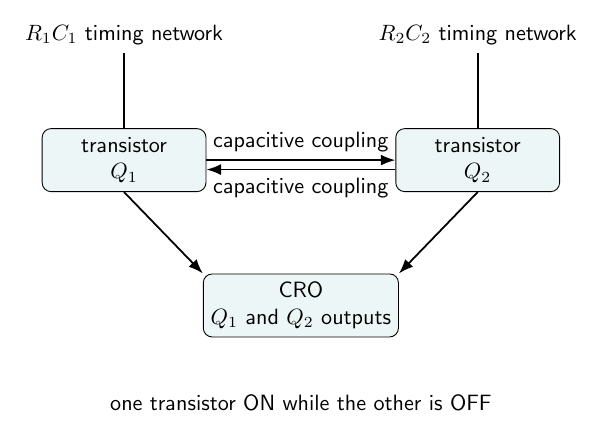
An astable multivibrator has two transistor switching stages coupled so that only one transistor is strongly conducting at a time. Suppose transistor $Q_1$ is ON and $Q_2$ is OFF. The capacitor connected to the base of $Q_2$ charges through its resistor until the base voltage reaches the switching level. Then $Q_2$ turns ON, its collector voltage falls, and the capacitive coupling drives $Q_1$ OFF. The same process occurs in the opposite direction.
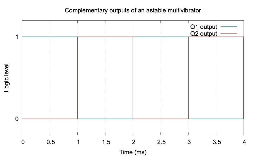
Since neither state is stable, the circuit repeatedly changes state without an external trigger and produces a square or rectangular wave. For a symmetrical circuit with equal timing components,
\[T\approx1.386RC,\qquad f=\frac{1}{T}.\]The measured period is obtained from the CRO time scale by counting the horizontal divisions for one complete cycle.
Observations
| $R$ (kohm) | $C$ (microfarad) | Calculated period $T$ (ms) | CRO period (ms) | Frequency (Hz) |
|---|---|---|---|---|
| 4.7 | 0.10 | 0.65 | 0.68 | 1471 |
| 10.0 | 0.10 | 1.39 | 1.42 | 704 |
| 10.0 | 0.22 | 3.05 | 3.12 | 321 |
| 22.0 | 0.22 | 6.70 | 6.82 | 147 |
Graph
Calculation
For $R=10$ kohm and $C=0.10$ microfarad,
\[T=1.386(10\times10^3)(0.10\times10^{-6})=1.386\text{ ms},\]and
\[f=\frac{1}{1.386\times10^{-3}}=722\text{ Hz}.\]Result
The circuit operates as a free-running oscillator. For the selected timing components its frequency is approximately
\[\boxed{f\approx704\text{ Hz}}.\]Viva Questions
- Why is the circuit called astable? It has no stable state and changes continuously between two quasi-stable switching conditions.
- What determines the frequency? Mainly the timing resistors and capacitors.
- Why are the two outputs complementary? When one transistor conducts, the other is driven into the cut-off state.


Discussion