

13 Jul 2026
Characteristics of a Geiger-Muller Counter and Determination of Its Operating Voltage
Aim
To plot the counting characteristic of a Geiger-Muller counter and determine its starting voltage, plateau region, plateau slope, and operating voltage.
Apparatus
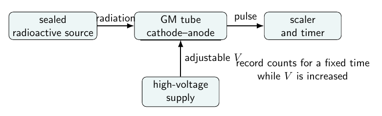
Geiger-Muller tube, GM scaler, high-voltage supply, radioactive check source, source holder, stopwatch or preset timer, and connecting leads.
Experimental arrangement
Theory
An entering alpha, beta, or gamma ray produces ion pairs in the gas filling of the GM tube. The applied electric field drives the electrons towards the central anode. Above the starting voltage, the electrons gain enough energy between collisions to produce further ionisation, so one original event gives a large Townsend avalanche and a detectable pulse.
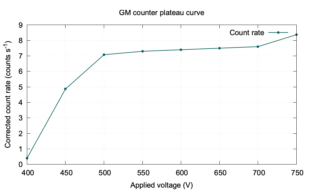
As the voltage is increased, the count rate first rises rapidly. It then becomes nearly independent of voltage over a range called the plateau. The midpoint of this stable region is selected as the operating voltage. Beyond the plateau, continuous discharge may occur and the tube can be damaged.
The plateau slope is expressed as the percentage increase in count rate per $100$ V:
\[\text{plateau slope}=\frac{N_2-N_1}{N_1}\frac{100}{V_2-V_1}\times100\ \%\text{ per }100\text{ V}.\]The operating voltage is taken near the centre of the plateau,
\[V_0=\frac{V_1+V_2}{2},\]where $V_1$ and $V_2$ are the lower and upper plateau limits.
Observations
Background count in $60$ s: $N_B=18$.
| Applied voltage (V) | Source count in 60 s | Corrected count rate (counts s$^{-1}$) |
|---|---|---|
| 400 | 42 | 0.40 |
| 450 | 310 | 4.87 |
| 500 | 443 | 7.08 |
| 550 | 456 | 7.30 |
| 600 | 462 | 7.40 |
| 650 | 468 | 7.50 |
| 700 | 474 | 7.60 |
| 750 | 520 | 8.37 |
Graph
Calculation
The plateau extends approximately from $V_1=550$ V to $V_2=700$ V. Hence
\[V_0=\frac{550+700}{2}=625\text{ V}.\]Using $N_1=7.30\ \text{s}^{-1}$ and $N_2=7.60\ \text{s}^{-1}$,
\[\text{plateau slope}=\frac{7.60-7.30}{7.30}\frac{100}{150}\times100=2.74\%\text{ per }100\text{ V}.\]Result
The operating voltage of the GM counter is
\[\boxed{V_0=625\text{ V}}.\]The plateau slope is approximately $2.74\%$ per $100$ V.
Precautions
- Increase the high voltage slowly and never operate in the continuous-discharge region.
- Keep the source position and counting time fixed for all readings.
- Follow the laboratory rules for handling radioactive sources.
Viva Questions
- What is the GM plateau? It is the voltage range over which the count rate changes only slightly with applied voltage.
- Why is the operating voltage chosen near the plateau centre? Small voltage fluctuations then produce only a small change in count rate.
- Why is a quenching gas used? It stops the discharge after one radiation event and prevents continuous discharge.


Discussion