

13 Jul 2026
B-H Loop and Hysteresis Loss of a Ferromagnetic Core
Experimental arrangement
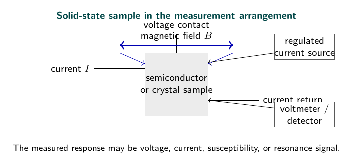
Aim
To plot the B-H curve of an iron sample and determine its hysteresis energy loss.
Apparatus
Iron ring or transformer core, primary and secondary coils, CRO, integrator circuits, AC supply, and voltmeter.
Theory
In an unmagnetised ferromagnetic specimen, magnetic domains are oriented so that their resultant magnetisation is nearly zero. A current in the magnetising winding produces the field
\[H=\frac{NI}{l},\]where $N$ is the number of turns and $l$ is the mean magnetic path. The field moves domain walls and rotates magnetic moments, creating magnetisation $M$. The flux density is
\[B=\mu_0(H+M).\]At small $H$, reversible wall motion dominates. At larger fields, domains aligned with the field grow until the material approaches saturation. When $H$ returns to zero, some alignment remains; the corresponding flux density is the remanence $B_r$. A reverse field of magnitude $H_c$, called the coercive field, is required to reduce $B$ to zero. Repeating the cycle produces the closed B-H hysteresis loop.
In the CRO method, current through a series resistor is proportional to $H$ and is applied to the horizontal input. A secondary or search winding produces
\[e_s=-N_sA\frac{dB}{dt}.\]An RC integrator converts this induced voltage into a vertical voltage proportional to $B$. The X-Y display therefore traces $B$ against $H$ directly. The energy dissipated per unit volume in one complete magnetisation cycle is
\[W_h=\oint H\,dB.\]It equals the geometrical loop area after applying the horizontal and vertical calibration factors. At frequency $f$, the hysteresis power loss per unit volume is $P_h=fW_h$.
Observations
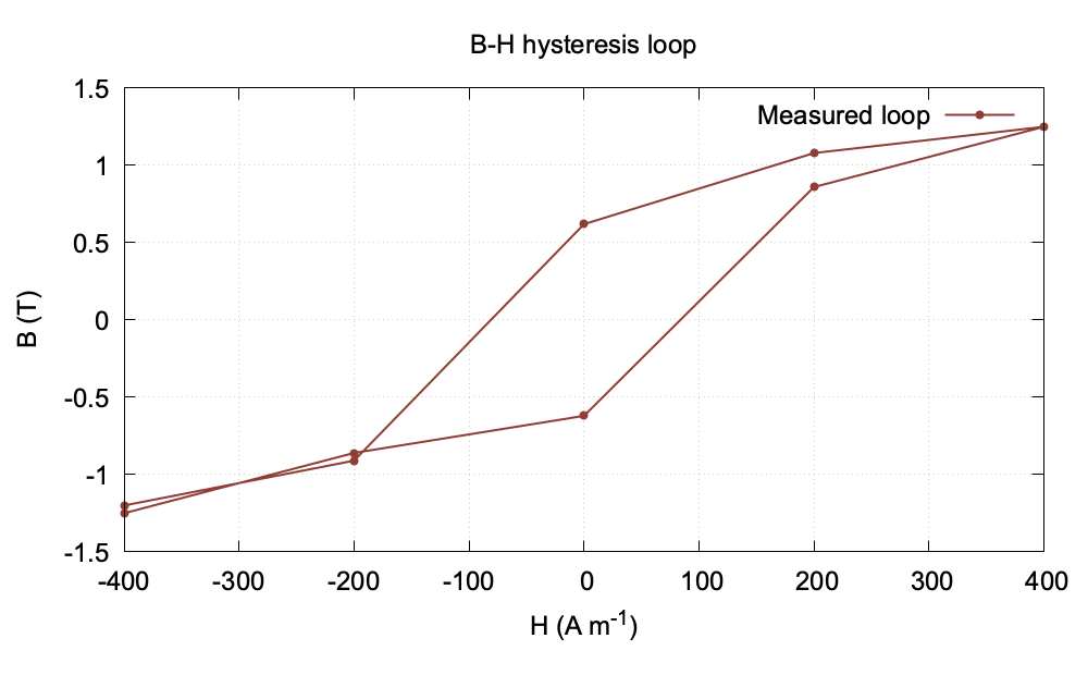
| $H$ (A m$^{-1}$) | $B$ (T) on increasing field | $B$ (T) on decreasing field |
|---|---|---|
| 0 | 0.00 | 0.62 |
| 100 | 0.48 | 0.73 |
| 200 | 0.86 | 0.91 |
| 300 | 1.10 | 1.08 |
| 400 | 1.25 | 1.20 |
Retentivity: $B_r=0.62\,\text{T}$; coercivity: $H_c=95\,\text{A m}^{-1}$.
Graph
Calculation
At zero applied field on the decreasing branch, the specimen retains $B_r=0.62$ T. The field required to bring the induction to zero is read from the horizontal axis as $H_c=95$ A m$^{-1}$. The area enclosed by the loop is obtained from the plotted points; for this trial curve it is approximately
\[W_h=\oint H\,dB\approx0.18\,\text{J m}^{-3}\text{ cycle}^{-1}.\]Thus a larger loop area would mean greater energy loss in repeated magnetisation.
Result
The iron sample shows a closed hysteresis loop with
\[\boxed{B_r=0.62\,\text{T}},\qquad \boxed{H_c=95\,\text{A m}^{-1}}.\]The loop area gives the hysteresis energy loss per unit volume per cycle.
Precautions
- Demagnetise the core before beginning.
- Avoid saturation of the CRO input.
- Use a calibrated integrator.
- Keep the frequency constant while comparing losses.
Viva Questions
- What is retentivity? It is the residual magnetisation when the applied field is reduced to zero.
- What is coercivity? It is the reverse field required to reduce the residual induction to zero.
- What does the loop area represent? Energy dissipated per unit volume per cycle.


Discussion