

13 Jun 2026
Characteristics of an 8-Bit ADC and R-2R Ladder DAC
Experimental arrangement
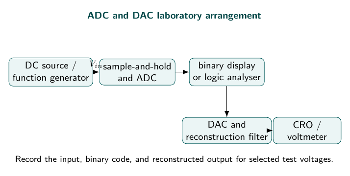
Aim
To determine the resolution and transfer characteristics of an 8-bit analogue-to-digital converter and an R-2R ladder digital-to-analogue converter.
Apparatus
8-bit ADC and R-2R DAC trainer, regulated supply, variable DC input, function generator, CRO, digital multimeter, and patch cords.
Theory
An analogue voltage can take any value in a continuous interval, but an $n$-bit digital system can represent only $2^n$ distinct codes. An ADC therefore performs three operations: it samples the input, compares it with discrete decision levels, and encodes the selected level as a binary number. For a unipolar range from 0 to $V_{ref}$, the ideal one-least-significant-bit step is
\[q=\frac{V_{ref}}{2^n}.\]If $V_i$ lies inside the range, the ideal output count is approximately $D=\operatorname{round}(V_i/q)$. Replacing a continuous value by the nearest level introduces quantisation error, bounded by approximately $\pm q/2$ for an ideal rounding converter. A successive-approximation ADC tests the most significant bit first, uses an internal DAC and comparator to decide whether that bit is retained, and repeats the process down to the least significant bit. This gives a fixed conversion time of roughly $n$ comparison cycles.
The R-2R DAC performs the reverse conversion using only two resistance values, $R$ and $2R$. At each ladder junction, the equivalent resistance looking toward the less significant bits remains $2R$. Consequently, successive bits contribute binary-weighted currents in the ratio $1/2:1/4:1/8:\cdots$. An op-amp sums these currents. Ignoring the sign of an inverting output,
\[V_o=V_{ref}\left(\frac{b_{n-1}}2+\frac{b_{n-2}}4+\cdots+\frac{b_0}{2^n}\right) =V_{ref}\frac{D}{2^n}.\]The full-scale code $2^n-1$ therefore gives $V_{ref}(1-2^{-n})$, one LSB below $V_{ref}$. Offset error shifts the whole transfer curve, gain error changes its slope, non-linearity bends it, and settling time limits how soon a DAC reading may be taken after the code changes.
Observations
For an 8-bit, $5\,\text{V}$ converter, $q=19.53\,\text{mV}$.
| Input voltage (V) | ADC code | DAC output (V) |
|---|---|---|
| 0.50 | 00011010 | 0.508 |
| 1.00 | 00110011 | 0.996 |
| 2.50 | 10000000 | 2.510 |
| 4.00 | 11001101 | 4.000 |
Calculation
For an 8-bit converter with $V_{ref}=5$ V, the ideal step size is
\[q=\frac{V_{ref}}{2^8}=\frac{5}{256}=0.01953\,\text{V}=19.53\,\text{mV}.\]For an input of $0.50$ V, the ideal ADC count is
\[D=\frac{0.50}{0.01953}=25.6\approx26.\]The decimal number 26 is $00011010_2$, which is the observed code. The corresponding ideal DAC output is
\[V_o=\frac{D V_{ref}}{2^8}=\frac{26(5)}{256}=0.5078\,\text{V},\]close to the observed $0.508$ V. The difference is less than one converter count.
Result
The converter produces a monotonic digital code and the DAC output follows the input within approximately one least-significant-bit error.
Precautions
Use a stable reference voltage, connect the ground correctly, allow settling time, and do not change code lines while the output is being measured.
Viva Questions
- What is resolution? The smallest input change represented by one digital count.
- What is quantisation error? The difference between the actual analogue value and its nearest digital level.
- What is monotonicity? The output does not decrease when the input code increases.


Discussion