

13 Jun 2026
Measurement of Optical-Fibre Patch-Cord Loss in dB
Aim
To measure the insertion loss of an optical-fibre patch cord in decibels.
Apparatus
LED or laser fibre source, optical power meter, reference patch cord, test patch cord, fibre connectors, and cleaning kit.
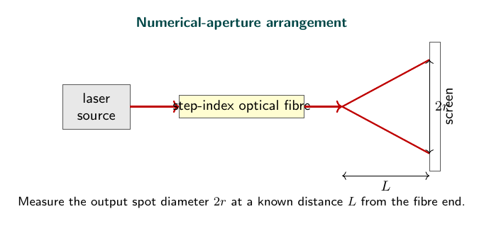
Experimental arrangement
Theory
An optical fibre confines light to its core by total internal reflection because the core refractive index is slightly greater than that of the cladding. The guided optical power nevertheless decreases during propagation. Material absorption converts part of it to heat, microscopic index fluctuations cause Rayleigh scattering, and sharp bends couple guided modes into radiation modes. A practical patch cord also includes connector and coupling losses at its ends.
Insertion loss is measured by substitution. First, the source is connected to the power meter through the reference arrangement and the reference power $P_{ref}$ is stored. The test cord is then inserted without changing wavelength, source drive, detector range, or connector alignment. If the transmitted power becomes $P_{out}$, the insertion loss is
\[L=10\log_{10}\left(\frac{P_{ref}}{P_{out}}\right)\,\text{dB}.\]Optical power in dBm is defined by
\[P(\text{dBm})=10\log_{10}\left[\frac{P(\text{mW})}{1\ \text{mW}}\right].\]Therefore, when both readings are in dBm,
\[L=P_{ref}(\text{dBm})-P_{out}(\text{dBm}).\]This value is the loss of the complete patch-cord insertion, not simply the intrinsic fibre attenuation per kilometre. For short cords, connector repeatability may exceed the propagation loss. The connectors must therefore be cleaned and re-seated consistently, the cord must not be bent below its minimum bend radius, and several insertion readings should be averaged.
Observations
| Patch cord | Reference power (dBm) | Output power (dBm) | Loss (dB) |
|---|---|---|---|
| 1 m multimode | -3.2 | -4.1 | 0.9 |
| 3 m multimode | -3.2 | -4.6 | 1.4 |
| 5 m multimode | -3.2 | -5.0 | 1.8 |
Calculation
For the 1 m patch cord, the reference and output readings are $-3.2$ dBm and $-4.1$ dBm. Therefore,
\[L=P_{ref}-P_{out}=(-3.2)-(-4.1)=0.9\,\text{dB}.\]For the 5 m cord,
\[L=(-3.2)-(-5.0)=1.8\,\text{dB}.\]The loss therefore increases by $0.9$ dB between these two trial cords.
Result
The insertion loss increases with patch-cord length and connector number.
Viva Questions
- Why is a reference reading taken? To remove the source and meter baseline from the loss measurement.
- What is dBm? Optical power expressed relative to 1 mW.
- Why should connectors be cleaned? Dust produces additional coupling loss.


Discussion