

13 Jun 2026
Verification of Thevenin's and Norton's Theorems
Aim
To verify Thevenin’s and Norton’s theorems for a linear DC resistive network.
Apparatus
DC supply, resistors, load resistor, voltmeter, ammeter, potentiometer or decade resistance box, and connecting leads.
Experimental arrangement
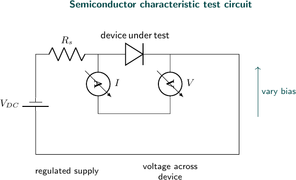
Theory
Any two-terminal network made from linear elements and sources has a terminal voltage-current relation of the form
\[V=V_{th}-IR_{th}.\]The constant term is found by opening the load, for which $I=0$ and $V=V_{oc}=V_{th}$. The slope is the resistance seen from the terminals. To determine it directly, independent voltage sources are replaced by their internal resistance, ideally a short circuit, and independent current sources by an open circuit. Dependent sources, if present, must remain active and a test source must be used. Thevenin’s theorem therefore replaces the complete linear network by the open-circuit voltage $V_{th}$ in series with $R_{th}$.
At the opposite limiting condition, shorting the terminals makes $V=0$ and gives
\[I_{sc}=I_N=\frac{V_{th}}{R_{th}}.\]Norton’s theorem represents the same terminal line by current source $I_N$ in parallel with $R_N$. Source transformation requires
\[R_N=R_{th},\qquad V_{th}=I_NR_N.\]When a finite load $R_L$ is connected, the two equivalent forms predict
\[I_L=\frac{V_{th}}{R_{th}+R_L}=I_N\frac{R_N}{R_N+R_L}.\]The theorem is verified by showing that the original network and both equivalents produce the same load current and voltage, not merely by comparing $V_{th}$ and $I_N$. The short-circuit current should be measured only when the source and network can safely supply it; otherwise it is calculated from the equivalent resistance.
Observations
| Arrangement | Load resistance (ohm) | Load current (mA) |
|---|---|---|
| original network | 1000 | 3.96 |
| Thevenin equivalent | 1000 | 3.94 |
| Norton equivalent | 1000 | 3.95 |
Calculation
For the trial network take the measured Thevenin parameters as $V_{th}=5.00$ V and $R_{th}=260\,\Omega$. The predicted load current for $R_L=1000\,\Omega$ is
\[I_L=\frac{V_{th}}{R_{th}+R_L}=\frac{5.00}{260+1000}=3.968\times10^{-3}\,\text{A}=3.97\,\text{mA}.\]The equivalent Norton current is
\[I_N=\frac{V_{th}}{R_{th}}=\frac{5.00}{260}=19.23\,\text{mA},\qquad R_N=R_{th}=260\,\Omega.\]Using the Norton form gives
\[I_L=I_N\frac{R_N}{R_N+R_L}=19.23\frac{260}{1260}=3.97\,\text{mA}.\]The observed currents, 3.96, 3.94, and 3.95 mA, differ from this ideal value by less than one percent.
Result
The load currents in the original, Thevenin-equivalent, and Norton-equivalent circuits agree within experimental error.
Viva Questions
- What is $V_{th}$? The open-circuit voltage at the output terminals.
- How is $R_{th}$ found? Deactivate independent sources and find the resistance seen from the terminals.
- What is the Norton current? The short-circuit current at the output terminals.


Discussion