

13 Jun 2026
Op-Amp Square and Triangular Waveform Generator with Sample-and-Hold Storage Amplifier
Aim
To generate square and triangular waves using an op-amp Schmitt trigger-integrator circuit and to study acquisition, hold, and droop in a sample-and-hold storage amplifier.
Apparatus
Dual op-amp IC, analogue switch or sample-and-hold IC, resistors, integrating and hold capacitors, dual regulated DC supply, sampling-pulse generator, dual-channel CRO, digital multimeter, breadboard, and leads.
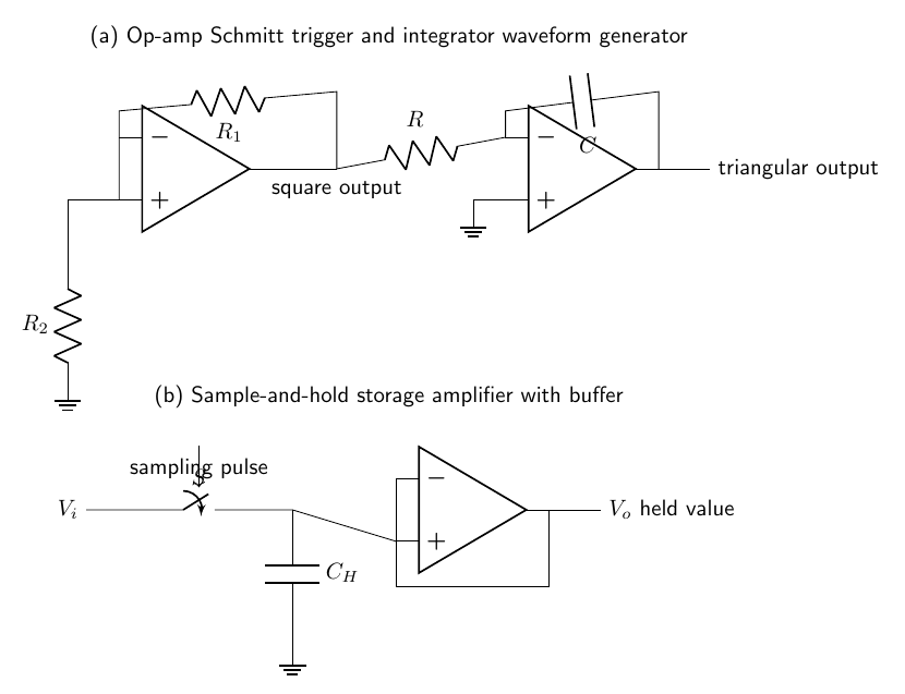
Circuit diagram
Theory
The waveform generator contains a comparator with positive feedback and an inverting integrator. Positive feedback makes the comparator a Schmitt trigger with two switching thresholds. If $R_1$ connects the output to the non-inverting input and $R_2$ connects that input to ground, the feedback fraction is
\[\beta=\frac{R_2}{R_1+R_2},\]and the thresholds are $V_{UT}=+\beta V_{sat}$ and $V_{LT}=-\beta V_{sat}$. Suppose the comparator output is $+V_{sat}$. The integrator output then changes linearly because
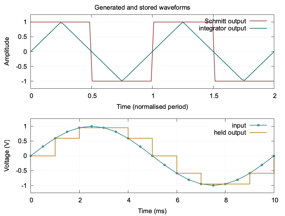
\[\frac{dV_T}{dt}=-\frac{V_{sat}}{RC}.\]When the triangular voltage reaches one threshold, the comparator changes state; the integrator slope reverses and continues to the opposite threshold. This repeated switching produces simultaneous square and triangular outputs. The time to traverse $2\beta V_{sat}$ is $2\beta RC$, so
\[T=4\beta RC,\qquad f=\frac{1}{4\beta RC}.\]In the storage amplifier, the electronic switch closes during the sampling pulse. The hold capacitor $C_H$ then charges toward the instantaneous input; this is the acquisition interval. When the switch opens, the stored charge ideally remains constant, so the capacitor retains the sampled voltage. A voltage follower isolates $C_H$ from the load because it has high input resistance and low output resistance. Leakage current and op-amp bias current slowly change the stored charge, producing a droop rate
\[\left|\frac{dV_o}{dt}\right|\simeq\frac{I_{leak}}{C_H}.\]Thus a practical storage amplifier is described by acquisition time, hold step, aperture uncertainty, and droop rate, rather than ordinary voltage gain alone.
Procedure
- Assemble the Schmitt trigger and integrator, check the op-amp supply polarities, and connect both outputs to the CRO.
- Measure the upper and lower switching thresholds, square-wave period, and triangular-wave peak values.
- Change $R$ or $C$ and verify that the frequency varies approximately as $1/RC$.
- Connect the signal to the sample-and-hold input and apply narrow sampling pulses to the analogue switch.
- Observe the input and held output simultaneously. Record the output immediately after each pulse.
- Hold a fixed sample for a known interval and measure the fall in output to determine droop rate.
Observations
For the generator, $R_1=10.0\ \text{k}\Omega$, $R_2=10.0\ \text{k}\Omega$, $R=10.0\ \text{k}\Omega$, and $C=0.0100\ \mu\text{F}$.
| Quantity | Calculated value | Observed value |
|---|---|---|
| Feedback fraction $\beta$ | 0.500 | 0.498 |
| Square-wave frequency | 5.00 kHz | 4.92 kHz |
| Square output | $\pm10.2$ V | $\pm10.0$ V |
| Triangular output | $\pm5.10$ V | $\pm4.95$ V |
For $C_H=0.10\ \mu\text{F}$:
| Sampling time (ms) | Input at sampling (V) | Held output (V) |
|---|---|---|
| 1 | 0.59 | 0.58 |
| 2 | 0.95 | 0.94 |
| 4 | 0.59 | 0.58 |
| 6 | -0.59 | -0.58 |
| 7 | -0.95 | -0.94 |
| 9 | -0.59 | -0.58 |
During a separate hold test, the output changed from $0.940\ \text{V}$ to $0.920\ \text{V}$ in $10.0\ \text{ms}$.
Waveforms
Calculation
Here
\[\beta=\frac{10}{10+10}=0.500.\]Therefore,
\[f=\frac{1}{4\beta RC} =\frac{1}{4(0.500)(10.0\times10^3)(0.0100\times10^{-6})} =5.00\ \text{kHz}.\]The percentage difference of the observed frequency is
\[\frac{|5.00-4.92|}{5.00}\times100=1.6\%.\]The storage-amplifier droop rate is
\[\left|\frac{dV_o}{dt}\right| =\frac{0.940-0.920}{10.0\times10^{-3}} =2.0\ \text{V s}^{-1}.\]The corresponding effective leakage current is
\[I_{leak}=C_H\left|\frac{dV_o}{dt}\right| =(0.10\times10^{-6})(2.0)=0.20\ \mu\text{A}.\]Result
The circuit generated square and triangular waves at $4.92\ \text{kHz}$, within $1.6\%$ of the calculated value. The sample-and-hold stage reproduced the sampled input levels and had a measured droop rate of $2.0\ \text{V s}^{-1}$ for $C_H=0.10\ \mu\text{F}$.
Precautions
- Verify the dual supply and common ground before inserting the op-amps.
- Keep the input within the analogue switch and op-amp common-mode ranges.
- Use a high-impedance buffer and a short connection to the hold capacitor.
- Make the sampling pulse long enough for acquisition but short compared with the signal period.
- Measure droop away from switching transients and allow for CRO probe loading.
Viva Questions
- Why does the Schmitt trigger have two threshold voltages? Positive feedback makes the switching level depend on the present output state, producing hysteresis.
- Why is the integrator output triangular? A constant square input produces a constant capacitor current and therefore a linear rate of change of output voltage.
- What is acquisition time? It is the time required after closing the switch for the hold capacitor voltage to settle within a specified error of the input.
- Why is a voltage follower used after the hold capacitor? It prevents the load from rapidly discharging the capacitor while providing a low-resistance output.
- What causes droop? Switch leakage, capacitor leakage, dielectric absorption, and op-amp input bias current gradually change the stored charge.
Maxima Code
Download the Maxima calculation for the waveform generator and storage amplifier.


Discussion