

14 Jul 2026
Use of Multimeter for Basic Electrical Measurements
Aim
To use a digital multimeter for measuring resistance, AC voltage, DC voltage, DC current, capacitance, and continuity of a fuse.
Apparatus
Digital multimeter, resistors, DC power supply, AC supply, capacitor, connecting leads, and fuse wire.
Figure
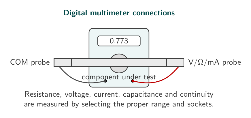
Principle
A multimeter combines voltmeter, ammeter, ohmmeter, capacitance meter, and continuity tester in one instrument. For voltage measurement it is connected in parallel. For current measurement it is connected in series. For resistance and capacitance measurement the component should be disconnected from any live circuit.
Observations
| Quantity | Trial 1 | Trial 2 | Trial 3 | Mean value |
|---|---|---|---|---|
| Resistance (k$\Omega$) | 0.771 | 0.773 | 0.774 | 0.773 |
| DC voltage (V) | 4.98 | 5.01 | 5.00 | 4.997 |
| Capacitance ($\mu$F) | 9.8 | 10.1 | 10.0 | 9.97 |
Continuity test:
| Object tested | Multimeter indication | Conclusion |
|---|---|---|
| Good fuse | Beep sound | Fuse is continuous |
| Broken fuse | No beep sound | Fuse is open |
Result
The multimeter was used successfully for measuring resistance, voltage, capacitance, and continuity. The observed mean resistance was $0.773\text{ k}\Omega$, the DC voltage was $4.997\text{ V}$, and the capacitance was $9.97\,\mu\text{F}$.
Precautions
- Select the correct function and range before connecting the multimeter.
- Do not measure resistance or capacitance in a live circuit.
- Use the current socket only for current measurement.
- Connect the voltmeter in parallel and the ammeter in series.
- Start with a higher range if the value is not known.
Viva Questions
-
Why is a voltmeter connected in parallel?
It measures potential difference across a component, so it must be connected across that component. -
Why is an ammeter connected in series?
The same current must pass through the ammeter and the circuit element. -
What does continuity mode check?
It checks whether a conducting path is complete or broken. -
Why should resistance not be measured in a live circuit?
The internal battery of the multimeter is used for resistance measurement; an external voltage can damage the meter and give wrong readings. -
What is the role of the COM terminal?
It is the common terminal connected to the black probe.
Maxima Code
The calculation can be checked with this file: multimeter-calculation.mac.


Discussion