

13 Jul 2026
Testing Diodes and Transistors Using a Multimeter
practical
ug-iv
electronics
multimeter
diode
transistor
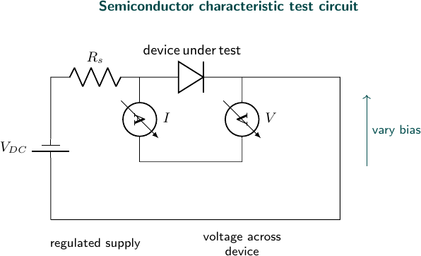
Experimental arrangement
Aim
To identify semiconductor devices and test the condition of diodes and transistor junctions using a digital multimeter.
Apparatus
Digital multimeter, silicon diode, LED, NPN transistor, PNP transistor, and connecting leads.
Theory
A diode conducts strongly in forward bias and offers high resistance in reverse bias. A transistor contains two PN junctions. For an NPN transistor, the base-emitter and base-collector junctions conduct when the positive probe is connected to the base; for a PNP transistor the polarity is reversed.
Observations
| Device/test | Forward reading | Reverse reading | Inference |
|---|---|---|---|
| Silicon diode | $0.68\,\text{V}$ | OL | Good diode |
| LED | $1.86\,\text{V}$ | OL | Good LED |
| NPN, base-emitter | $0.69\,\text{V}$ | OL | Junction good |
| NPN, base-collector | $0.66\,\text{V}$ | OL | Junction good |
| NPN, collector-emitter | OL | OL | No short circuit |
Result
The tested silicon diode, LED, and NPN transistor are in working condition. The transistor is identified as NPN from the polarity of its two conducting junctions.
Precautions
- Remove the device from the circuit before testing it.
- Do not test a charged capacitor on the resistance range.
- Use the diode-test range for junction-voltage readings.
- Do not exceed the current limit of the multimeter.
Viva Questions
- What does OL indicate? It indicates that the measured resistance is beyond the selected range or the junction is reverse biased.
- Why does an LED show a larger forward voltage? Its semiconductor material has a larger effective band gap.
- How are transistor terminals identified? By testing the two junctions and comparing their conducting polarities.
- Why must power be removed? External circuit paths can give false readings and may damage the meter.


Discussion