

13 Jul 2026
Frequency Response of an RC-Coupled Transistor Amplifier
practical
ug-iv
electronics
amplifier
frequency-response
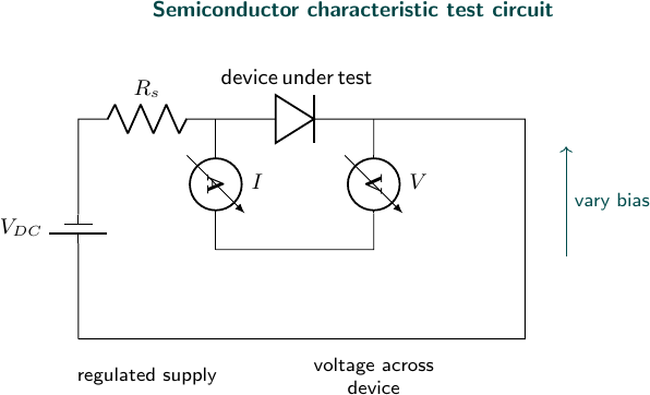
Experimental arrangement
Aim
To determine the frequency response and bandwidth of a single-stage RC-coupled transistor amplifier.
Apparatus
RC-coupled amplifier circuit, signal generator, CRO, DC supply, and connecting leads.
Theory
The voltage gain of an amplifier depends on frequency. It is nearly constant in the mid-frequency region and decreases at low frequency because of coupling capacitors and at high frequency because of transistor and stray capacitances. The bandwidth is
\[\text{Bandwidth}=f_H-f_L,\]where $f_L$ and $f_H$ are the lower and upper half-power frequencies.
Observations
Input amplitude: $20\,\text{mV}$.
| Frequency (Hz) | Output amplitude (V) | Voltage gain |
|---|---|---|
| 50 | 0.42 | 21 |
| 100 | 0.76 | 38 |
| 500 | 1.02 | 51 |
| 1000 | 1.05 | 52.5 |
| 5000 | 1.04 | 52 |
| 10000 | 0.98 | 49 |
| 20000 | 0.74 | 37 |
| 50000 | 0.43 | 21.5 |
The half-power gain is approximately $52.5/\sqrt2=37.1$.
Result
From the response curve, $f_L\approx100\,\text{Hz}$ and $f_H\approx20\,\text{kHz}$. Therefore,
\[\boxed{\text{Bandwidth}\approx19.9\,\text{kHz}}.\]Precautions
- Keep the input amplitude constant while changing frequency.
- Avoid overloading the amplifier input.
- Use a common ground for the generator and CRO.
- Measure the output after the waveform becomes stable.
Viva Questions
- Why is the coupling capacitor used? It passes AC while blocking DC bias.
- Why does gain fall at low frequency? The reactance of coupling and bypass capacitors becomes large.
- Why does gain fall at high frequency? Transistor and stray capacitances become significant.
- What is the mid-band gain? It is the nearly constant gain in the central frequency range.


Discussion