

13 Jul 2026
V-I Characteristics of a Zener Diode and Voltage Regulation
practical
ug-iv
electronics
zener-diode
regulator
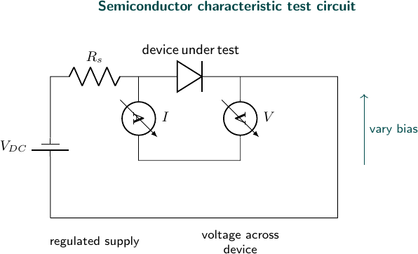
Experimental arrangement
Aim
To plot the V-I characteristics of a Zener diode and study its action as a voltage regulator.
Apparatus
Zener diode, regulated DC supply, series resistor, voltmeter, milliammeter, load resistor, and connecting wires.
Theory
A Zener diode is operated in reverse breakdown. In this region a large change in current produces only a small change in voltage. Hence it can maintain an approximately constant load voltage. The breakdown voltage obtained from the characteristic is the Zener voltage $V_Z$.
Observations
| Reverse voltage (V) | Zener current (mA) |
|---|---|
| 4.8 | 0.2 |
| 5.0 | 0.8 |
| 5.1 | 2.0 |
| 5.15 | 4.0 |
| 5.20 | 6.0 |
At $V_{in}=9\,\text{V}$, $R_s=470\,\Omega$, and $R_L=1\,\text{k}\Omega$:
| Load current (mA) | Regulated output (V) |
|---|---|
| 1.0 | 5.08 |
| 2.0 | 5.10 |
| 3.0 | 5.11 |
Result
The Zener voltage is approximately $V_Z=5.1\,\text{V}$, and the circuit maintains an output close to $5.1\,\text{V}$ over the measured load-current range.
Precautions
- Always use a series resistor to limit Zener current.
- Do not exceed the rated power of the diode.
- Increase reverse voltage slowly.
- Check the polarity before switching on the supply.
Viva Questions
- Why does a Zener diode regulate voltage? Its reverse voltage changes very little in the breakdown region.
- What is the purpose of the series resistor? It limits current and protects the diode.
- What is dynamic resistance? It is the small-signal ratio $\Delta V_Z/\Delta I_Z$ in breakdown.
- Can a Zener diode be used without a resistor? No, because the current may exceed its safe limit.


Discussion