

13 Jul 2026
Dielectric Constant of a Material as a Function of Frequency
practical
ug-vi
dielectric
frequency
capacitance
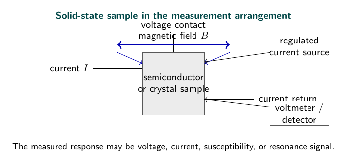
Experimental arrangement
Aim
To determine the dielectric constant of a material at different frequencies.
Apparatus
Parallel-plate capacitor, dielectric specimen, LCR meter, oscillator, and connecting leads.
Theory
For a parallel-plate capacitor, insertion of a dielectric changes the capacitance from $C_0$ to $C$. The relative dielectric constant is
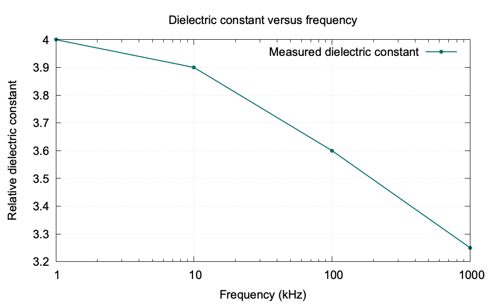
\[\epsilon_r=\frac{C}{C_0}.\]At high frequency, orientational polarisation cannot follow the applied field and the dielectric constant generally decreases.
Observations
| Frequency (kHz) | $C_0$ (pF) | $C$ (pF) | $\epsilon_r$ |
|---|---|---|---|
| 1 | 102 | 408 | 4.00 |
| 10 | 101 | 394 | 3.90 |
| 100 | 100 | 360 | 3.60 |
| 1000 | 99 | 322 | 3.25 |
Graph
Result
The dielectric constant decreases from approximately $4.0$ at low frequency to $3.25$ at $1\,\text{MHz}$ in the sample range.
Precautions
- Keep the dielectric specimen flat between the plates.
- Remove stray capacitance by proper instrument zeroing.
- Use screened leads at high frequency.
Viva Questions
- What is dielectric polarisation? It is the displacement or orientation of bound charges in an electric field.
- Why does dielectric constant fall with frequency? Slow polarisation mechanisms cannot follow rapid field reversals.
- What is relative permittivity? It is the ratio of the material permittivity to vacuum permittivity.


Discussion